Content for TS 37.340 Word version: 17.3.0
1…
4…
4.2…
4.3…
5…
7…
8…
9
10…
10.2…
10.2.2…
10.3…
10.3.2
10.4…
10.5…
10.5.2
10.6
10.7…
10.8…
10.9…
10.10…
10.11…
10.12…
10.12.2
10.13…
10.14…
10.15
10.16…
10.17…
10.18…
10.19…
11…
A
B…
10.9 eNB/gNB to Master Node change p. 79
10.9.1 EN-DC p. 79
The eNB to Master Node change procedure is used to transfer context data from a source eNB to a target MN that adds an SN during the handover.
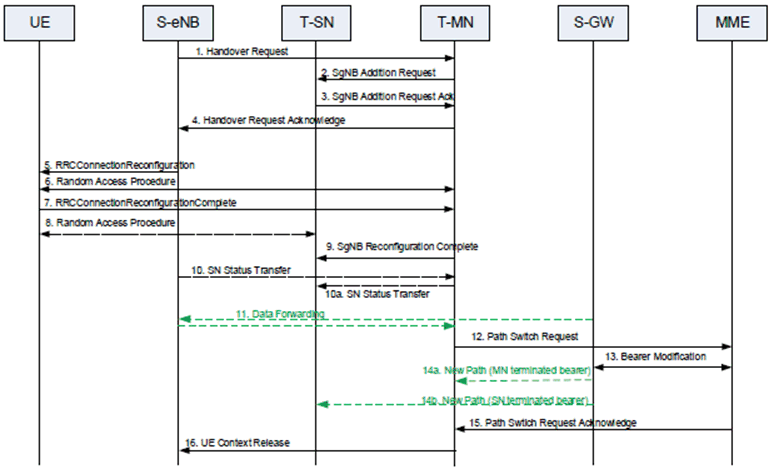
Figure 10.9.1-1 shows an example signaling flow for eNB to Master Node change:
Step 1.
The source eNB starts the handover procedure by initiating the X2 Handover Preparation procedure.
Step 2.
The target MN sends SgNB Addition Request to the target SN.
Step 3.
The target SN replies with SgNB Addition Request Acknowledge. If data forwarding is needed, the target SN provides forwarding addresses to the target MN.
Step 4.
The target MN includes within the Handover Request Acknowledge message a transparent container to be sent to the UE as an E-UTRA RRC message, including a NR RRC configuration message which also includes the SCG configuration, to perform the handover, and may also provide forwarding addresses to the source eNB.
Step 5.
The source eNB triggers the UE to apply the new configuration.
Step 6/7.
The UE synchronizes to the target MN and replies with RRCConnectionReconfigurationComplete message.
Step 8.
If configured with bearers requiring SCG radio resources, the UE synchronizes to the target SN.
Step 9.
If the RRC connection reconfiguration procedure was successful, the target MN informs the target SN.
Step 10.
For bearers using RLC AM, the source eNB sends the SN Status Transfer message, which the target MN forwards then to the target SN, if needed.
Step 11.
Data forwarding from the source eNB takes place.
Step 12-15.
The target MN initiates the S1 Path Switch procedure.
Step 16.
The target MN initiates the UE Context Release procedure towards the source eNB.
10.9.2 MR-DC with 5GC p. 80
The ng-eNB/gNB to MN change procedure is used to transfer UE context data from a source ng-eNB/gNB to a target MN that adds an SN during the handover. Only the cases where the source node and the target MN belong to the same RAT (i.e. they are both ng-eNBs or both gNBs) are supported.

Figure 10.9.2-1 shows an example signalling flow for ng-eNB/gNB to MN change:
Step 1.
The source ng-eNB/gNB starts the handover procedure by initiating the Xn Handover Preparation procedure.
Step 2.
The target MN sends SN Addition Request to the target SN.
Step 3.
The target SN replies with SN Addition Request Acknowledge. If data forwarding is needed, the target SN provides forwarding addresses to the target MN.
Step 3a.
For SN terminated bearers using MCG resources, the target MN provides Xn-U DL TNL address information in the Xn-U Address Indication message.
Step 4.
The target MN includes within the Handover Request Acknowledge message the SN RRC reconfiguration message to be sent to the UE that includes the SCG configuration to perform the handover, and may also provide forwarding addresses to the source ng-eNB/gNB.
Step 5.
The source ng-eNB/gNB triggers the UE to perform handover and apply the new configuration.
Step 6/7.
The UE synchronizes to the target MN and replies with MN RRC reconfiguration complete message including the SN RRC reconfiguration complete message.
Step 8.
If configured with bearers requiring SCG radio resources, the UE synchronizes to the target SN.
Step 9.
If the RRC connection reconfiguration procedure was successful, the target MN informs the target SN via SN Reconfiguration Complete message.
Step 10.
For bearers using RLC AM, the source ng-eNB/gNB sends the SN Status Transfer message, which the target MN forwards then to the target SN, if needed.
Step 11.
Data forwarding from the source ng-eNB/gNB takes place.
Step 12-15.
The target MN initiates the PDU Session Path Switch procedure.
Step 16.
The target MN initiates the UE Context Release procedure towards the source ng-eNb/gNB.
![]()
![]()
![]()