Content for TS 32.101 Word version: 17.0.0
5.4 Service Oriented Architecture (SOA)
5.4.1 Basic elements of SOA
5.4.2 Aggregation of SOA basic elements
5.4.3 Information transfer bus
5.4.4 SOA elements within the Management reference model
5.4.5 SOA-based representation of the Management Reference Model
5.4.6 SOA-supporting Solution Set
...
...
5.4 Service Oriented Architecture (SOA) |R9| p. 22
5.4.1 Basic elements of SOA p. 22
The basic building block of SOA is a service. In the context of this document, the word service is used to denote the various kinds of network management services, provided or provisioned by and consumed by network management applications. This type of network management services are distinct from those that are consumed by, say, mobile phone subscribers. One example of this type of network management service is one that is used for the management of alarm information of a network. Another example can be one that is used for the management of the transfer of large amount of network management information in files.
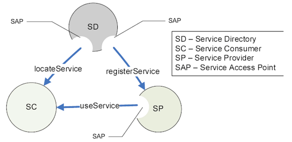
A service, in the context of this document, is considered a black box whose internal design and characteristics are of no relevance. A service performs tasks that satisfy a specific set of requirements. A service is realized by a Service Provider (SP) entity. This entity, the SP, is responsible to register (re: using the registerService offered by SD to SP of the following diagram) its provisioned service in one or more Service Directory (SD) entities. Service Consumers (SCs), without prior knowledge of the kind of services provisioned and the service access point (SAP) of the provisioned service, can consult the SD for the information (re: using the locateService offered by SD to SC of the following diagram). Once the SC discovers the wanted provisioned service and its associated SAP, it can contact the SP and start consuming the wanted provisioned service (re: using the useService offered by SP to SC of the following diagram).
Using the basic interaction scenario described above, a new SC can be installed and activated without prior knowledge of its wanted service SAP(s). As long as a) the new SC is given the SAP of the SD and b) the SP providing the wanted service has registered its service with the SD, the new SC can discover the availability of its wanted service and its SAP, and thus, can begin to access the service wanted.
Similarly, a new SP can be installed and activated (i.e. to provision its service) without prior knowledge of its potential SC(s). It is required to register its provisioned service with SD(s).
The SD is a special kind of SP. It provides two kinds of services. One service supports the registration of the identity, availability and SAP of the provisioned service (re: registerService offered by SD to SP of the following diagram). The other service supports the discovery of services (re: locateService offered by SD to SC of the following diagram).
The SDs' SAPs for providing registration of provisioned service should be made known to all SPs. The SDs' SAPs for discovery of provisioned service should be made known to all SCs. The means by which these SAPs are make known to SCs and SPs are not subject to standardization.
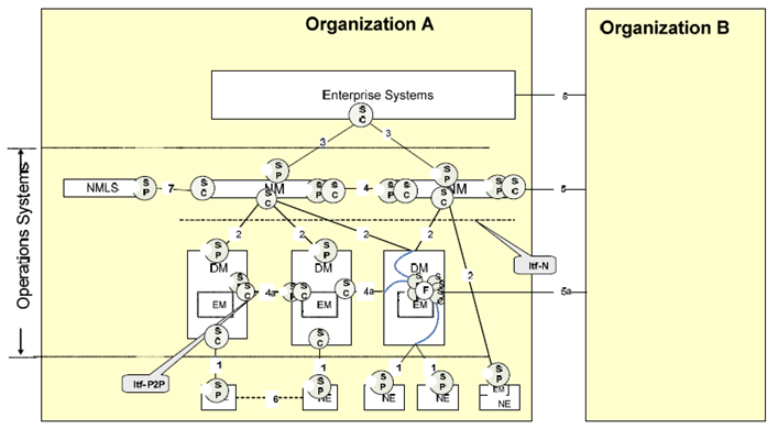
The NE, EM, NM and DM of Figure 1 are entities that contain a SP. The DM, NM and Enterprise System of Figure 1 are entities that contain a SC.
The following diagram depicts the key elements of SOA and their relations. The relation is depicted by an arrow with a label. The arrow end indicates the consumer of the network management service. The other end indicates the provider of the service. The label identifies the service.

5.4.2 Aggregation of SOA basic elements p. 23
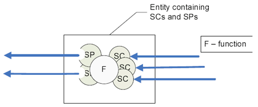
An entity can have one or more SCs and SPs at the same time. This entity can consume services from SPs, add its own value using internal function such as service aggregation, correlation, service request redirection, information store and forward service, etc (re F of the following diagram), and provide a new set of enhanced service to other potential SCs. To play the role of SP, this entity would need to register its enhanced service with SD. The diagram below depicts such entity.
The DM and NM of Figure 1 are of this entity kind.

5.4.3 Information transfer bus p. 24
SPs, SCs and SDs transfer information among themselves. For example, a SC would send a service request to a SP. In SOA, a bus-like concept is used to depict the capability of such information transfer. This bus-like concept support a key attribute of SOA in that its basic elements, namely SP, SC and SDs, are all loosely-coupled, e.g. their bindings are to be established on need and at run-time basis.
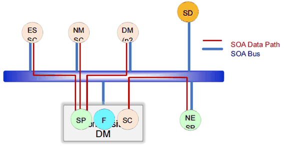
The following Figure depicts the loosely-coupled SOA elements supported by the Information transfer bus.

5.4.4 SOA elements within the Management reference model p. 24
This clause shows the placement of SOA basic elements SPs and SCs within the Management reference model (see Figure 1).

For example, the right-hand side DM (a Management reference model construct) of Figure 2d shows an entity that is an aggregation of SOA basic elements (see clause 5.4.2). This entity produces and consumes services (see Figure of clause 5.4.2). It has two SPs and three SCs. In addition, it has an F function that mediates between services DM provides and the services DM requires. The DM services are provided to one SC of the neighboring DM and to two SCs of two NMs. The DM requires services from two SPs of the two NEs. One of the SPs of this DM provides a network management service via the Type 2 interface. One of the SPs supports the peer-to-peer protocol by offering services to its neighboring DM via Interface 4a. Three SCs of this DM are consumer of network management services offered by two NEs via the Type 1 interface.
To avoid cluttering the Figure, SDs are not shown in Figure 2d. Conceptually, SDs can be positioned anywhere in the Management reference model. For example, the most likely configuration is to have SDs placed within the Operations Systems boundary. They can either be embedded inside NM and/or DM and/or stand-alone. Note that an SD embedded, say in DM-1, does not imply that this particular SD would/could only register services provided by DM-1. To avoid cluttering the Figure, F function is only shown in one DM but all DMs and NMs can have F function as well.
The question if the protocols supporting the locateService and registerService (see Figure 2a) are of Type 1 or Type 2 or Type 4, etc can only be answered if the placement of SD and its clients (i.e. SC and SP) in the Management reference model are known.
5.4.5 SOA-based representation of the Management Reference Model p. 25
This section provides another SOA-based view of the 3GPP Management Reference Model that includes the paths where network management information would flow (SOA data path). This view is derived from and in accordance with Figure 4: "Placement of SOA elements on Management reference model".

Figure 5: SOA-based representation of the 3GPP Management Reference Model
(⇒ copy of original 3GPP image)
(⇒ copy of original 3GPP image)
Figure 5 depicts the communication over the SOA bus. Serving management entities (i.e. SP) are connected to the SOA bus with functionality exposed as a service. SPs can be registered and discovered via the SD, and they can also be composite services that connect to or reuse other SPs (i.e Composite DM). Consuming management entities (i.e. SC) are also connected to the SOA bus and can discover available services via the SD, and subsequently use services of SPs.
5.4.6 SOA-supporting Solution Set p. 26
SOA-supporting Solution Set definitions can be found in Annex C.