Content for TS 23.502 Word version: 18.5.0
1…
4.2.2.2.2
4.2.2.2.3…
4.2.2.3…
4.2.3…
4.2.3.3
4.2.4…
4.2.6
4.2.7…
4.2.9…
4.2.11…
4.2.11.5…
4.3…
4.3.2.2.2
4.3.2.2.3…
4.3.3…
4.3.3.3
4.3.4…
4.3.4.3
4.3.5…
4.3.5.2…
4.3.5.4…
4.3.5.6…
4.3.6…
4.4…
4.5…
4.9…
4.9.1.3…
4.9.2…
4.11…
4.11.1…
4.11.1.2.2
4.11.1.2.3
4.11.1.3…
4.11.1.3.3…
4.11.1.4…
4.11.1.5…
4.11.2…
4.11.3…
4.12…
4.12.6…
4.12a…
4.12b…
4.13…
4.13.4…
4.13.6…
4.14…
4.15…
4.15.3.2.5…
4.15.4…
4.15.6…
4.15.6.7…
4.15.6.13…
4.15.6.14…
4.15.9…
4.15.9.4…
4.15.13…
4.15.13.4…
4.16…
4.16.4…
4.16.8…
4.16.11…
4.16.14…
4.16.15…
4.17…
4.17.9…
4.18…
4.19…
4.22…
4.23…
4.23.7…
4.23.7.3.3
4.23.7.3.4…
4.23.9…
4.23.9.4…
4.23.11…
4.24…
4.25…
4.25.6…
4.26…
5…
5.2.3…
5.2.5…
5.2.6…
5.2.7…
5.2.8…
5.2.9…
5.2.12…
5.2.18…
A…
E…
F…
G
H…
4.26 Network Function/NF Service Context Transfer Procedures
4.26.1 General
4.26.2 NF/NF Service Context Transfer Push Procedure
4.26.3 NF/NF Service Context Transfer Pull procedure
4.26.4 Context Transfer due to decommissioning
4.26.5 SMF Service Context Transfer procedures
4.27 Procedures for Enhanced Coverage Restriction Control via NEF
4.28 Subscription-based distribution of timing information
4.28.1 General
4.28.2 5G Access Stratum-based Time Distribution
4.28.3 (g)PTP-based Time Distribution
...
...
4.26 Network Function/NF Service Context Transfer Procedures |R16| p. 663
4.26.1 General p. 663
Network Function/NF Service Context Transfer Procedures allow transfer of Service Context of a NF/NF Service from a Source NF/NF Service Instance to the Target NF/NF Service Instance, e.g. before the Source NF/NF Service can gracefully close its NF/NF Service. If SMF sets are deployed this applies from an SMF instance within an SMF set to an SMF instance of another SMF set.
A request (push procedure, see clause 4.26.2) or response (pull procedure, see clause 4.26.3) from a Source NF/NF Service Instance to a Target NF/NF Service Instance contains either
- the context being transferred, e.g. SM context (direct mode); or
- optionally, an endpoint address from which Target NF/NF Service Instance can retrieve the context, see TS 29.501 (indirect mode).
4.26.2 NF/NF Service Context Transfer Push Procedure p. 664
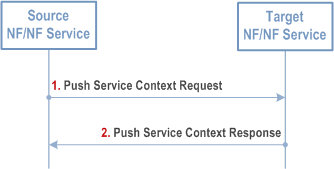
Step 1.
When triggered, the Source NF/NF Service acting as NF Service Consumer sends its Context (e.g. UE Context or SM context) to the Target NF/NF Service acting as NF Service producer. This may trigger several other procedures that ensure all necessary NF/NF Services are being updated and set up with necessary information about the new context location.
Step 2.
The NF Service Consumer receives the response indicating the result of the operation (successful or not successful). When all procedures have been executed successfully the Target NF/NF Service can continue to serve the original NF Service Consumers of the Source NF/NF Service, which e.g. can be shut down gracefully.
4.26.3 NF/NF Service Context Transfer Pull procedure p. 664
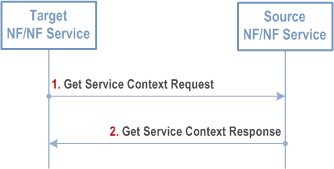
Step 1.
When triggered, the Target NF/NF Service as an NF Service Consumer requests a Context (e.g. UE context or SM context) from the Source NF as a NF Service Producer. This may trigger several other procedures that ensure all necessary NF/NF services are being updated and set up with necessary information about the new context location.
Step 2.
The NF Service Consumer receives the Context and the operation was successful. When all procedures have been executed successfully the Target NF/NF Service can continue to serve the original NF Service Consumers of the Source NF/NF Service, which e.g. can be shut down gracefully.
4.26.4 Context Transfer due to decommissioning p. 665
In the case of decommissioning, the Old NF may inform NRF that it is about to be decommissioned. NRF will in this case not include the NF profile of the Old NF in any discovery result from the NF/NF service discovery procedure. The NRF will also notify any consumers subscribed to changes to this resource.
4.26.5 SMF Service Context Transfer procedures p. 665
4.26.5.1 General p. 665
This clause lists the context-specific transfer procedures between different SMF Sets supporting the same DNN/S-NSSAI pair supported for SM Contexts (i.e. SMF contexts).
4.26.5.2 I-SMF Context Transfer procedure p. 665
Old I-SMF triggered from O&M procedure sends Nsmf_PDUSession_SMContextStatusNotify (I-SMF transfer indication, New SMF ID or SMF set ID) to AMF.
Steps 2-25 in clause 4.23.4.3 follows, where in step 2 AMF selects the indicated I-SMF, or selects the I-SMF from the indicated SMF set.
4.26.5.3 SMF Context Transfer procedure, LBO or no Roaming, no I-SMF p. 665
In the case of dynamic IP address assignment (IPv4 address and/or IPv6 prefix), the procedure in Figure 4.26.5.3-1 assumes that, if the UE IP address is received from Old SMF, the control of the IP address(es) assigned by Old SMF is moved to New SMF by O&M procedures. New SMF is in full control of the concerned IP address(es) when the transfer is complete.
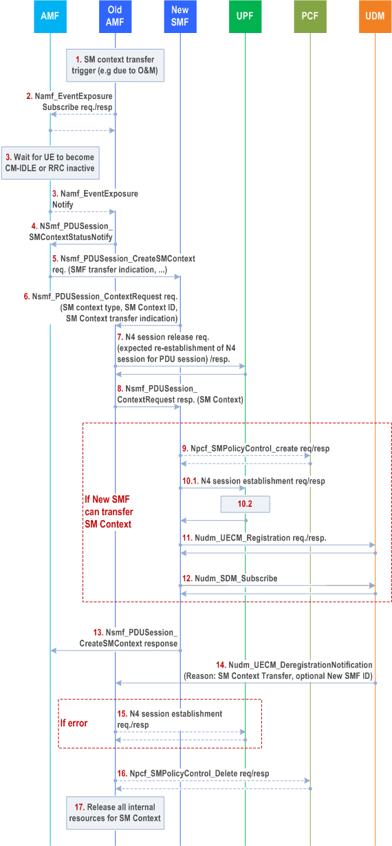
Step 1.
SM context transfer is triggered, e.g. by OAM to Old SMF including SUPI, PDU session ID and New SMF ID or SMF set ID. The SMF selection by using SMF set ID not applicable when the IP range is managed by SMF.
Step 2.
[Conditional - depending on current subscription] Old SMF subscribes to events when UE status becomes CM-IDLE or CM-CONNECTED with RRC_INACTIVE state (Namf_EventExposure_Subscribe ).
Step 3.
[Conditional - depending on the event] The AMF detects the monitored event occurs and sends the event report by means of Namf_EventExposure_Notify message, to Old SMF.
Step 4.
From Old SMF to AMF Nsmf_PDUSession_SMContextStatusNotify (SMF transfer indication, Old SMF ID, New SMF ID or SMF set ID from Step 1, PDU Session ID, SUPI, SM Context ID).
Step 5.
AMF, or SCP if delegated discovery is used, uses New SMF ID or SMF set ID to select New SMF and sends Nsmf_PDUSession_CreateSMContext request (PDU Session ID, Old SMF ID, SM Context ID in Old SMF, UE location info, Access Type, RAT Type, Operation Type, SMF transfer indication). The same PDU Session ID as received in step 4 is used. If the AMF receives the service request from the UE for the PDU session(s) affected by this procedure the AMF delays the transaction with the SMF until the step 13 completes. If the AMF receives the UE context transfer request from the other AMF due to the UE mobility, the AMF defers the response until the step 13 completes. Also, to avoid infinite waiting time, the AMF starts a locally configured guard timer upon sending the request to the SMF and the AMF decides the procedure has failed at expiry of the guard timer.
Step 6.
From New SMF to Old SMF SMF Nsmf_PDUSession_ContextRequest request (SM Context type, SM Context ID, SMF transfer indication). If New SMF is not capable to transfer this SM Context (e.g. it is not responsible for the IP range), steps 9 to 12 are skipped.
Step 7.
Old SMF releases the N4 session with the UPF by sending a flag notifying the UPF about the expected re-establishment of the N4 session for the same PDU session. Based on this, if supported, the UPF should delay the release of the N4 session up to step 10.2 to allow for uninterrupted packet handling until the N4 session is re-established by New SMF.
Step 8.
From Old SMF to New SMF Nsmf_PDUSession_ContextRequest response (SM Context or endpoint address where New SMF can retrieve SM Context). The SM Context includes the IP address(es) if the PDU session is of type IPv4, IPv6 or IPv4v6, or the Ethernet MAC address(es) if the PDU session if of type Ethernet as well as the UPF to be selected by New SMF. Old SMF starts a timer to monitor the SMF context transferring process.
Step 9.
[Conditional] If dynamic PCC is used for the PDU Session, New SMF sets up a new policy association towards PCF.
Step 10.1.
UPF receives a N4 session establishment request for the same PDU session from step 7. The parameters from step 8 and if applies, step 9 are used.
Step 10.2.
New SMF performs a full re-establishment of the N4 session, establishing a new N4 session. All information related to the N4 session of Old SMF that is not used by the N4 session of New SMF is removed from UPF if not already done.
Step 11.
New SMF registers to UDM. The information stored at the UDM includes SUPI, SMF identity and the associated DNN and PDU Session ID.
Step 12.
New SMF subscribes to subscription changes for the UE.
Step 13.
From New SMF to AMF: Nsmf_PDUSession_CreateSMContext response. If this response indicates a redirect (e.g. another SMF in the set), the procedure moves to step 5 with the indicated endpoint address as target.
Step 14.
UDM notifies Old SMF that it is deregistered for the PDU Session by sending Nudm_UECM_DeregistrationNotification , optionally including New SMF ID
Step 15.
[Conditional] If 14 was not received and the timer from step 8 expires, Old SMF re-establishes the N4 session. The UPF may for the purpose use the information stored in step 7. In this case, the procedure ends here.
Step 16.
[Conditional] If Nudm_UECM_DeregistrationNotification in step 14 was received, Old SMF removes its policy association with PCF. Any changes to the QoS rules need to be sent to the UE when it becomes active.
Step 17.
Old SMF releases any internal resources corresponding to the indicated PDU session. Subscribers to SMContextStatusNotify for the transferred SM context are notified of the context transfer and optionally of the new location of the transferred SM context.
4.27 Procedures for Enhanced Coverage Restriction Control via NEF |R16| p. 668
4.27.1 General p. 668
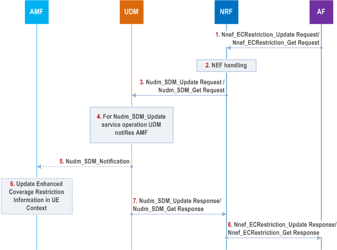
The support for Enhanced Coverage Restriction Control via NEF enables AF to query status of Enhanced Coverage Restriction or enable/disable Enhanced Coverage Restriction per individual UEs. Figure 4.27.1-1 shows the procedure for Enhanced Coverage Restriction Control via NEF.
Step 1.
The AF may enable or disable Enhanced Coverage Restriction or query the status of Enhanced Coverage Restriction by sending the Nnef_ECRestriction_Update Request or Nnef_ECRestriction_Get Request respectively. Both the service operations require GPSI and AF Identifier as required input and optionally MTC Provider Information.
Step 2.
Based on operator policies, if the AF is not authorized to perform the request (e.g. if the SLA does not allow for it) or if the AF has exceeded its quota or rate of submitting Enhanced Coverage Requests, the NEF performs Step 8 and provides a cause value appropriately indicating the failure result.
Step 3.
The NEF sends the Nudm_ParameterProvision_Update Request to update the subscription data for Enhanced Coverage Restriction. The NEF sends the Nudm_SDM_Get Request service operation to query the status of Enhanced Coverage Restriction.
Step 4.
The UDM checks the GPSI and examines whether any included parameters are in the range acceptable by the operator, whether Enhanced Coverage Restriction is supported by the serving NF (i.e. AMF in this case). If this check fails, the UDM provides a cause value indicating the reason for failure condition to the NEF in step 7
In the case of Nudm_ParameterProvision_Update Request, the UDM sets the Enhanced Coverage Restriction information to the appropriate value and procedure continues to step 5.
In the case of Nudm_SDM_Get Request, the UDM may retrieve the status of Enhanced Coverage Restriction information from UDR using Nudr_DM_Query Request and skip steps 5 and 6.
Step 5.
The UDM sends Nudm_SDM_Notification and provide AMF with updates Enhanced Coverage Restriction information.
Step 6.
The AMF updates the Enhanced Coverage Restriction information stored in the UE context. The AMF will transfer Enhanced Coverage Restriction information stored as part of its UE context during AMF change.
Step 7.
The UDM sends the Nudm_ParameterProvision_Update Response or Nudm_SDM_Get Response to the NEF.
Step 8.
The NEF sends the Nnef_ECRestriction_Update Response or Nnef_ECRestriction_Get Response to the AF.
4.28 Subscription-based distribution of timing information |R18| p. 669
4.28.1 General p. 669
The distribution of 5G Clock (5G Access Stratum-based Time Distribution) and the (g)PTP domain synchronization ((g)PTP-based Time Distribution) may be controlled based on subscription data.
4.28.2 5G Access Stratum-based Time Distribution p. 669
4.28.2.1 Control of access stratum time synchronization service without AF request p. 669
The control of 5G Access Stratum-based Time Distribution for a UE is performed by the AMF according to parameters retrieved in the Access and Mobility Subscription data.
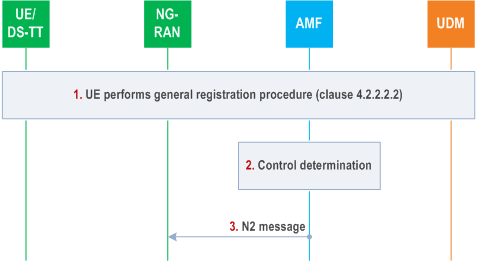
Step 1.
The UE performs the registration procedure as described in clause 4.2.2.2.2. The AMF retrieves the Access and Mobility Subscription data including the Access Stratum Time Synchronization Service Authorization. The Access and Mobility Subscription data may further include the Uu time synchronization error budget, one or more periods of start and stop times defining active times, a coverage area, clock quality detail level, and the acceptance criteria for the UE, as described in clause 5.27.1.11 of TS 23.501.
As part of this, the AMF shall, if supported, store the 5G access stratum time distribution indication (enable, disable), the Uu time synchronization error budget, clock quality detail level and clock quality acceptance criteria, and the UE reconnection indication in the UE context in AMF.
Step 2.
The AMF performs the control according to the subscription data as follows.
If the AMF receives start and stop times then the AMF sends the message to the NG-RAN to enable or disable the 5G access stratum time distribution according to the expiry of start and stop times if the UE is in CM-CONNECTED state. If the UE is in CM-IDLE state when a Start time condition is met, then the AMF pages the UE and provides the 5G access stratum distribution indication to NG-RAN as part of the subsequent service request procedure initiated by the UE in the response to the paging.
If the AMF received Time Synchronization Coverage Area information as part of the Access and Mobility Subscription data including the Access Stratum Time Synchronization Service Authorization, the AMF determines if the Coverage Area information shall trigger an activation or deactivation of the access stratum time distribution:
Step 3.
- If the UE has moved inside the Coverage Area, then the AMF determines to enable access stratum time distribution for the UE.
- If the UE has moved outside the Coverage Area, then the AMF determines to disable access stratum time distribution for the UE.
The AMF sends N2 message (UE Context Modification Request) to the NG-RAN. The AMF sends the 5G access stratum time distribution indication (enable, disable), the Uu time synchronization error budget, clock quality detail level and clock quality acceptance criteria when they are available, to NG-RAN during mobility registration, AM policy modification, Service Request, N2 Handover and Xn handover as specified in TS 38.413. The NG-RAN node shall, if supported, store the information in the UE Context. Based on this information, the NG-RAN node provides the 5GS access stratum time to the UE according to the Uu time synchronization error budget as provided by the TSCTSF (if supported by UE and NG-RAN) and NG-RAN provides timing synchronization status reports to the UE (as described in clause 4.15.9.5.2).
4.28.3 (g)PTP-based Time Distribution p. 670
4.28.3.1 Control of (g)PTP time synchronization service without AF request p. 670
The TSCTSF may use the subscription data to control the (g)PTP-based time distribution without AF request.
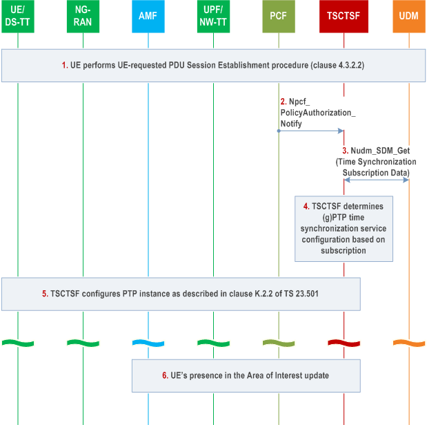
Step 1.
The UE performs the UE-requested PDU Session Establishment.
Step 2.
The PCF determines if the PDU Session is potentially impacted by time synchronization service and invokes Npcf_PolicyAuthorization_Notify service operation to the TSCTSF discovered and selected for time synchronization to indicate there is a UE connected to a specific DNN/S-NSSAI configured for (g)PTP-based time distribution. The TSCTSF retrieves the UE SUPI using IP address and /or DNN/S-NSSAI from BSF as specified in the clause 4.15.10.
Step 3.
The TSCSTF uses the SUPI to retrieve the Time Synchronization Subscription Data available at the UDM.
Step 4.
The TSCTSF controls the (g)PTP-based time synchronization service based on the Time Synchronization Subscription Data as defined in clause 5.27.1.11 of TS 23.501. If the Time Synchronization Subscription Data contains:
Step 5.
- one or more Subscribed Time Synchronization Service ID(s) that can be mapped to PTP instance configuration(s), the TSCTSF determines if one or more of the PTP instance configurations match with the DNN/S-NSSAI of the given PDU Session. The TSCTSF stores information that the time-synchronization service cannot be controlled by an AF for the DNN/S-NSSAI of given SUPI.
- An indication whether an AF-requested (g)PTP time synchronization service is allowed for the given UE and DNN/S-NSSAI. If it is allowed, the TSCTSF determines that the time-synchronization service can be controlled by an AF for the DNN/S-NSSAI of given SUPI.
- If TSCTSF receives neither a) nor b), the TSCTSF assumes that the time-synchronization service cannot be applied for the given PDU session. The TSCTSF does not initiate the AF-session establishment with the PCF.
- If TSCTSF receives both a) and b) and both a) and b) contain the same DNN/S-NSSAI, TSCTSF determines that the time-synchronization service cannot be controlled by an AF for the DNN/S-NSSAI of given SUPI.
For each matching PTP instance configuration determined in step 4, if no PTP instance exists for the given PTP instance configuration, the TSCTSF initializes the PTP instance in 5GS as described in clause K.2.2 of TS 23.501. The TSCTSF configures a PTP port in DS-TT and adds it to the corresponding PTP instance in NW-TT as described in clause K.2.2 of TS 23.501. The TSCTSF uses the procedure in clause 4.15.9.4 to activate or modify the 5G access stratum time distribution for the UE.
If the PTP instance configuration referenced by the Time Synchronization Subscription data for the UE contains start and stop times or a coverage area, the TSCTSF updates the PTP port for the corresponding PTP instance as defined in clause 5.27.1.11 of TS 23.501. The TSCTSF uses the procedure in clause 4.15.9.4 to activate or deactivate the 5G access stratum time distribution for the UEs that are part of the impacted PTP instance.
Step 6.
If a coverage area is included in the subscription data for UE related to the PTP instance, TSCTSF discovers the AMF(s) serving the TA(s) defined for the time synchronization coverage area (Area of Interest) and subscribe to receive notifications in UEs presence in the Area of Interest. Based on the outcome the TSCTSF determines whether to activate or deactivate the time synchronization service for the impacted PTP instance. The TSCTSF will activate/deactivate the service by modifying the PTP instance configuration as described in clause K.2.2 of TS 23.501.