Content for TR 38.879 Word version: 18.0.0
1 Scope
2 References
3 Definitions of terms, symbols and abbreviations
4 General
5 Study failure scenarios associated with the gNB-CU-CP
6 Conclusion
...
...
1 Scope p. 5
The present document provides descriptions of failure scenarios associated with the gNB-CU-CP based on current architecture for the NG-RAN.
2 References p. 5
The following documents contain provisions which, through reference in this text, constitute provisions of the present document.
- References are either specific (identified by date of publication, edition number, version number, etc.) or non-specific.
- For a specific reference, subsequent revisions do not apply.
- For a non-specific reference, the latest version applies. In the case of a reference to a 3GPP document (including a GSM document), a non-specific reference implicitly refers to the latest version of that document in the same Release as the present document.
3 Definitions of terms, symbols and abbreviations p. 5
3.1 Terms p. 5
For the purposes of the present document, the terms given in TR 21.905 and the following apply. A term defined in the present document takes precedence over the definition of the same term, if any, in TR 21.905.
3.2 Symbols p. 5
For the purposes of the present document, the following symbols apply:
3.3 Abbreviations p. 5
4 General p. 5
The 3GPP split architecture for NG-RAN is described in TS 38.401. The NR gNB disaggregated architecture is characterized by the presence of a single gNB-CU-CP, which is in control of one or more gNB-DU(s) and one or more gNB-CU-UP(s) (Figure 4-1). Similarly, a gNB-DU may interact with multiple gNB-CU-UPs simultaneously for the same user context as long as they are controlled by the same gNB-CU-CP.
![Copy of original 3GPP image for 3GPP TS 38.879, Fig. 4-1: Overall architecture for separation of gNB-CU-CP and gNB-CU-UP TS 38.401 [2]](../img/tinv-38-879-4-1.gif)
Figure 4-1: Overall architecture for separation of gNB-CU-CP and gNB-CU-UP TS 38.401 [2]
(⇒ copy of original 3GPP image)
(⇒ copy of original 3GPP image)
The gNB-CU-CP may have specific configured data for each supported cell in the gNB, and a common gNB ID per PLMN. This identity is known in the gNB-DU and in neighbor gNBs, and it is also broadcasted in the served NR cells as part of the cell identity.

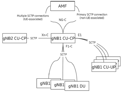
Figure 4-2: CP connections involving the AMF, gNB-CU-CP, gNB-CU-UP, and gNB-DUs.
(⇒ copy of original 3GPP image)
(⇒ copy of original 3GPP image)
There is one (active) CP anchor node per UE in the 5GC (AMF) and one (active) CP anchor per gNB in the NG-RAN (gNB-CU-CP). Figure 4-2 highlights the various CP connections going through the same gNB-CU-CP towards the AMF, to neighbor gNB-CU-CPs, to gNB-CU-UPs, and to gNB-DUs. All CP connections terminate in the gNB-CU-CP; if we only look at the logical architecture, the gNB-CU-CP may indeed be considered as a single point of failure.
For Operator, resiliency of public network is under national regulations or other operational constraints.
With regard to resiliency TS 38.401 includes only the following note:
Furthermore, multiple TNL associations toward the gNB-CU-CP are currently supported by the standard.
In the event of a failure at gNB-CU-CP, the likely outcome is that all user contexts could be affected and experience user service interruption.
This study handles failure scenarios for gNB-CU-CP, based on the current NG-RAN architecture.
Solutions for failure scenarios will not be addressed in this study.
The nodes shown in Figure 4-1 are logical nodes, i.e., they can be implemented as physical network functions (PNFs) using dedicated hardware (HW) infrastructures or as virtual network functions (VNFs) running as software (SW) functions (e.g., virtual machines (VMs) or cloud-native containers (CNFs)) on general purpose processors (GPPs; with or without HW acceleration support), e.g., in a cloud environment of a data center.
5 Study failure scenarios associated with the gNB-CU-CP p. 7
Various perspectives were considered by each company (see the informative Annex A for details).
A failure scenario for a deployment case with gNB-CU-CP at the antenna site (Distributed RAN/D-RAN) should not be of relevance for this study as an outage would impact the network performance only in a limited local area (similar to an outage of the co-located gNB-DU). Local resiliency measures may therefore be realized in the same way for both logical nodes (dependent on PNF/VNF implementation).
A more important scenario is the case when a gNB-CU-CP is deployed in a central office location of an operator's network. Those central locations may have transport network (TN) connections (e.g., via tree- or ring-based fibers) to several gNB-DUs located at different antenna sites. In such deployment case the gNB-CU-CP has the responsibility for proper operation of a large number of cells covering a wider regional area, i.e., an outage has a strong impact on overall user experience in a larger part of the mobile network. Each gNB-CU-CP may be connected via multiple TNL associations. As implicitly stated by the note in TS 38.401 gNB-DUs at antenna sites may be connected via the same or different TN links to one or several central locations (geo-redundancy) hosting gNB-CU-CP instances.
The following failure scenarios have been discussed:
- Hardware failure
- Software failure
- Transport network failure
- Power failure
- Entire gNB-CU-CP failure, e.g., due to natural disaster
6 Conclusion p. 7
In this TR, failure scenario in the existing gNB-CU-CP architecture from various perspectives were studied.
A failure affecting the entire (logical) gNB-CU-CP would impact all UEs served by the cells of the gNB-DUs connected to the gNB-CU-CP, resulting in those UEs being out of service for potentially long periods of time (dependent on type of failure and available resiliency measures). Current specification allows for some resiliency mechanisms via appropriate implementation (as described in TS 38.401) which can address a number of the failure scenarios.