Content for TS 38.473 Word version: 17.3.0
8.2 Interface Management procedures p. 30
8.2.1 Reset p. 30
8.2.1.1 General p. 30
The purpose of the Reset procedure is to initialise or re-initialise the F1AP UE-related contexts, in the event of a failure in the gNB-CU or gNB-DU. This procedure does not affect the application level configuration data exchanged during, e.g., the F1 Setup procedure.
The procedure uses non-UE associated signalling.
8.2.1.2 Successful Operation p. 30
8.2.1.2.1 Reset Procedure Initiated from the gNB-CU p. 30
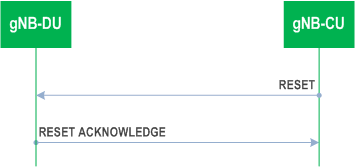
In the event of a failure at the gNB-CU, which has resulted in the loss of some or all transaction reference information, a RESET message shall be sent to the gNB-DU.
At reception of the RESET message the gNB-DU shall release all allocated resources on F1 and radio resources related to the UE association(s) indicated explicitly or implicitly in the RESET message and remove the indicated UE contexts including F1AP ID.
After the gNB-DU has released all assigned F1 resources and the UE F1AP IDs for all indicated UE associations which can be used for new UE-associated logical F1-connections over the F1 interface, the gNB-DU shall respond with the RESET ACKNOWLEDGE message. The gNB-DU does not need to wait for the release of radio resources to be completed before returning the RESET ACKNOWLEDGE message.
If the RESET message contains the UE-associated logical F1-connection list IE, then:
If the RESET message is received, any other ongoing procedure (except for another Reset procedure) on the same F1 interface related to a UE association, indicated explicitly or implicitly in the RESET message, shall be aborted.
- The gNB-DU shall use the gNB-CU UE F1AP ID IE and/or the gNB-DU UE F1AP ID IE to explicitly identify the UE association(s) to be reset.
- The gNB-DU shall include in the RESET ACKNOWLEDGE message, for each UE association to be reset, the UE-associated logical F1-connection Item IE in the UE-associated logical F1-connection list IE. The UE-associated logical F1-connection Item IEs shall be in the same order as received in the RESET message and shall include also unknown UE-associated logical F1-connections. Empty UE-associated logical F1-connection Item IEs, received in the RESET message, may be omitted in the RESET ACKNOWLEDGE message.
- If the gNB-CU UE F1AP ID IE is included in the UE-associated logical F1-connection Item IE for a UE association, the gNB-DU shall include the gNB-CU UE F1AP ID IE in the corresponding UE-associated logical F1-connection Item IE in the RESET ACKNOWLEDGE message.
- If the gNB-DU UE F1AP ID IE is included in the UE-associated logical F1-connection Item IE for a UE association, the gNB-DU shall include the gNB-DU UE F1AP ID IE in the corresponding UE-associated logical F1-connection Item IE in the RESET ACKNOWLEDGE message.
8.2.1.2.2 Reset Procedure Initiated from the gNB-DU p. 31
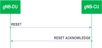
In the event of a failure at the gNB-DU, which has resulted in the loss of some or all transaction reference information, a RESET message shall be sent to the gNB-CU.
At reception of the RESET message the gNB-CU shall release all allocated resources on F1 related to the UE association(s) indicated explicitly or implicitly in the RESET message and remove the F1AP ID for the indicated UE associations.
After the gNB-CU has released all assigned F1 resources and the UE F1AP IDs for all indicated UE associations which can be used for new UE-associated logical F1-connections over the F1 interface, the gNB-CU shall respond with the RESET ACKNOWLEDGE message.
If the RESET message contains the UE-associated logical F1-connection list IE, then:
If the RESET message is received, any other ongoing procedure (except for another Reset procedure) on the same F1 interface related to a UE association, indicated explicitly or implicitly in the RESET message, shall be aborted.
- The gNB-CU shall use the gNB-CU UE F1AP ID IE and/or the gNB-DU UE F1AP ID IE to explicitly identify the UE association(s) to be reset.
- The gNB-CU shall in the RESET ACKNOWLEDGE message include, for each UE association to be reset, the UE-associated logical F1-connection Item IE in the UE-associated logical F1-connection list IE. The UE-associated logical F1-connection Item IEs shall be in the same order as received in the RESET message and shall include also unknown UE-associated logical F1-connections. Empty UE-associated logical F1-connection Item IEs, received in the RESET message, may be omitted in the RESET ACKNOWLEDGE message.
- If the gNB-CU UE F1AP ID IE is included in the UE-associated logical F1-connection Item IE for a UE association, the gNB-CU shall include the gNB-CU UE F1AP ID IE in the corresponding UE-associated logical F1-connection Item IE in the RESET ACKNOWLEDGE message.
- If the gNB-DU UE F1AP ID IE is included in a UE-associated logical F1-connection Item IE for a UE association, the gNB-CU shall include the gNB-DU UE F1AP ID IE in the corresponding UE-associated logical F1-connection Item IE in the RESET ACKNOWLEDGE message.
8.2.1.3 Abnormal Conditions p. 32
Not applicable.
8.2.2 Error Indication p. 32
8.2.2.1 General p. 32
The Error Indication procedure is initiated by a node in order to report detected errors in one incoming message, provided they cannot be reported by an appropriate failure message.
If the error situation arises due to reception of a message utilising UE associated signalling, then the Error Indication procedure uses UE associated signalling. Otherwise the procedure uses non-UE associated signalling.
8.2.2.2 Successful Operation p. 32
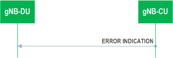
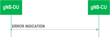
When the conditions defined in clause 10 are fulfilled, the Error Indication procedure is initiated by an ERROR INDICATION message sent from the receiving node.
The ERROR INDICATION message shall contain at least either the Cause IE or the Criticality Diagnostics IE. In case the Error Indication procedure is triggered by utilising UE associated signalling the gNB-CU UE F1AP ID IE and gNB-DU UE F1AP ID IE shall be included in the ERROR INDICATION message. If one or both of the gNB-CU UE F1AP ID IE and the gNB-DU UE F1AP ID IE are not correct, the cause shall be set to appropriate value, e.g., "Unknown or already allocated gNB-CU UE F1AP ID", "Unknown or already allocated gNB-DU UE F1AP ID" or "Unknown or inconsistent pair of UE F1AP ID".
8.2.2.3 Abnormal Conditions p. 33
Not applicable.
8.2.3 F1 Setup p. 33
8.2.3.1 General p. 33
The purpose of the F1 Setup procedure is to exchange application level data needed for the gNB-DU and the gNB-CU to correctly interoperate on the F1 interface. This procedure shall be the first F1AP procedure triggered for the F1-C interface instance after a TNL association has become operational.
The procedure uses non-UE associated signalling.
This procedure erases any existing application level configuration data in the two nodes and replaces it by the one received. This procedure also re-initialises the F1AP UE-related contexts (if any) and erases all related signalling connections in the two nodes like a Reset procedure would do.
8.2.3.2 Successful Operation p. 33
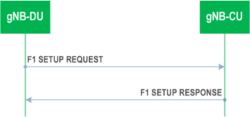
The gNB-DU initiates the procedure by sending a F1 SETUP REQUEST message including the appropriate data to the gNB-CU. The gNB-CU responds with a F1 SETUP RESPONSE message including the appropriate data.
The exchanged data shall be stored in respective node and used as long as there is an operational TNL association. When this procedure is finished, the F1 interface is operational and other F1 messages may be exchanged.
If the F1 SETUP REQUEST message contains the gNB-DU Name IE, the gNB-CU may use this IE as a human readable name of the gNB-DU. If the F1 SETUP REQUEST message contains the Extended gNB-DU Name IE, the gNB-CU may use this IE as a human readable name of the gNB-DU and shall ignore the gNB-DU Name IE if included.
If the F1 SETUP RESPONSE message contains the gNB-CU Name IE, the gNB-DU may use this IE as a human readable name of the gNB-CU. If the F1 SETUP RESPONSE message contains the Extended gNB-CU Name IE, the gNB-DU may use this IE as a human readable name of the gNB-CU and shall ignore the gNB-CU Name IE if included.
If the F1 SETUP REQUEST message contains the gNB-DU Served Cells List IE, the gNB-CU shall take into account as specified in TS 38.401.
For NG-RAN, the gNB-DU shall include the gNB-DU System Information IE and the TAI Slice Support List IE in the F1 SETUP REQUEST message.
The gNB-CU may include the Cells to be Activated List IE in the F1 SETUP RESPONSE message. The Cells to be Activated List IE includes a list of cells that the gNB-CU requests the gNB-DU to activate. The gNB-DU shall activate the cells included in the Cells to be Activated List IE and reconfigure the physical cell identity for cells for which the NR PCI IE is included.
If Cells to be Activated List Item IE is included in the F1 SETUP RESPONSE message, and the information for the cell indicated by the NR CGI IE includes the IAB Info IAB-donor-CU IE, the gNB-DU shall, if supported, apply the IAB STC Info IE therein to the indicated cell.
For NG-RAN, the gNB-CU shall include the gNB-CU System Information IE in the F1 SETUP RESPONSE message.
For NG-RAN, the gNB-DU may include Supported MBS FSA ID List IE in the Served Cell Information IE in the F1 SETUP REQUEST message. The gNB-CU may use it according to TS 38.300.
For NG-RAN, the gNB-DU may include the RAN Area Code IE in the F1 SETUP REQUEST message. The gNB-CU may use it according to TS 38.300.
For NG-RAN, the gNB-CU may include Available PLMN List IE, and optionally also Extended Available PLMN List IE in the F1 SETUP RESPONSE message, if the available PLMN(s) are different from what gNB-DU has provided in F1 SETUP REQUEST message, gNB-DU shall take this into account and only broadcast the PLMN(s) included in the received Available PLMN list(s).
For NG-RAN, the gNB-CU may include Available SNPN ID List IE in the F1 SETUP RESPONSE message. If the available SNPN(s) are different from what gNB-DU has provided in F1 SETUP REQUEST message, gNB-DU shall take this into account and only broadcast the SNPN(s) included in the received Available SNPN ID list.
The Latest RRC Version Enhanced IE shall be included in the F1 SETUP REQUEST message and in the F1 SETUP RESPONSE message.
If in F1 SETUP REQUEST message, the Cell Direction IE is present, the gNB-CU should use it to understand whether the cell is for UL or DL only. If in F1 SETUP REQUEST message, the Cell Direction IE is omitted in the Served Cell Information IE it shall be interpreted as that the Cell Direction is Bi-directional.
If the Intended TDD DL-UL Configuration IE is present in the F1 SETUP REQUEST message, the receiving gNB-CU shall use the received information for Cross Link Interference management and/or NR-DC power coordination. The gNB-CU may merge the Intended TDD DL-UL Configuration information received from two or more gNB-DUs. The gNB-CU shall consider the received Intended TDD DL-UL Configuration content valid until reception of an update of the IE for the same cell(s).
If the Aggressor gNB Set ID IE is included in the Served Cell Information IE in the F1 SETUP REQUEST message, the gNB-CU shall, if supported, take it into account.
If the Victim gNB Set ID IE is included in the Served Cell Information IE in the F1 SETUP REQUEST message, the gNB-CU shall, if supported, take it into account.
If the F1 SETUP REQUEST message contains the Transport Layer Address Info IE, the gNB-CU shall, if supported, take into account for IPSec tunnel establishment.
If the SFN Offset IE is contained in the Served Cell Information IE in the F1 SETUP REQUEST message, the gNB-CU shall, if supported, use this information to deduce the SFN0 offset of the reported cell.
If the F1 SETUP RESPONSE message contains the Transport Layer Address Info IE, the gNB-DU shall, if supported, take into account for IPSec tunnel establishment.
If the F1 SETUP RESPONSE message contains the Uplink BH Non-UP Traffic Mapping IE, the gNB-DU shall, if supported, consider the information therein for mapping of non-UP uplink traffic.
If the BAP Address IE is included in the F1 SETUP REQUEST, the receiving gNB-CU shall, if supported, consider the information therein for discovering the collocation of an IAB-DU and an IAB-MT.
If the F1 SETUP REQUEST message is received from an IAB-donor-DU, the gNB-CU shall, if supported, include the BAP Address IE in the F1 SETUP RESPONSE message.
If the F1 SETUP RESPONSE message contains the BAP Address IE, the gNB-DU shall, if supported, store the received BAP address and use it as specified in TS 38.340.
If the NR Cell PRACH Configuration IE is included in the Served Cell Information IE contained in the F1 SETUP REQUEST message, the gNB-CU may store the information, and forward it to other RAN nodes for RACH optimisation.
If the RedCap Broadcast Information IE is included in the Served Cell Information IE in the F1 SETUP REQUEST message, the gNB-CU may use this information to determine a suitable target in case of subsequent outgoing mobility involving RedCap UEs.
If the TAI NSAG Support List IE is included in the Served Cell Information IE in the F1 SETUP REQUEST message, the gNB-CU shall, if supported, use this information as specified in TS 23.501.
8.2.3.3 Unsuccessful Operation p. 35
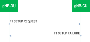
If the gNB-CU cannot accept the setup, it should respond with a F1 SETUP FAILURE and appropriate cause value.
If the F1 SETUP FAILURE message includes the Time To Wait IE, the gNB-DU shall wait at least for the indicated time before reinitiating the F1 setup towards the same gNB-CU.
8.2.3.4 Abnormal Conditions p. 35
Not applicable.
![]()
![]()
![]()