Content for TS 37.461 Word version: 17.1.0
1 Scope
2 References
3 Definitions and abbreviations
3.1 Definitions
3.2 Abbreviations
4 Iuant layer 1
4.1 General
4.2 RS485 option
...
...
1 Scope p. 5
The present document specifies the standards allowed to implement layer 1 on the Iuant interface for UTRA, E-UTRA and NR.
The specification of transmission delay requirements and O&M requirements are not in the scope of the present document.
The modem option of Iuant layer 1 specification in clause 4.3 applies to UTRA, E-UTRA BS and NR BS type 1-C.
2 References p. 5
The following documents contain provisions which, through reference in this text, constitute provisions of the present document.
- References are either specific (identified by date of publication, edition number, version number, etc.) or non-specific.
- For a specific reference, subsequent revisions do not apply.
- For a non-specific reference, the latest version applies. In the case of a reference to a 3GPP document (including a GSM document), a non-specific reference implicitly refers to the latest version of that document in the same Release as the present document.
[1]
TS 37.462: "UTRAN Iuant interface: Signalling transport".
[2]
ISO/IEC 8482 (1993-12): "Information technology - Telecommunications and information exchange between systems - Twisted pair multipoint interconnections".
[3]
TIA/EIA TSB89: "Application guidelines for TIA/EIA-485-A".
[4]
TS 25.101: "Technical Specification Group Radio Access Network; User Equipment (UE) radio transmission and reception (FDD)"
[5]
TS 36.101: "Evolved Universal Terrestrial Radio Access (E-UTRA); User Equipment (UE) radio transmission and reception"
[6]
TS 38.101-1: "NR; User Equipment (UE) radio transmission and reception (FDD)"
3 Definitions and abbreviations p. 5
3.1 Definitions p. 5
For the purposes of the present document, the following terms and definitions apply:
On-Off-Keying:
A modulation system in which a carrier is switched between two states, ON and OFF.
Common feeder cable:
Feeder cable where some antenna line devices (e.g. RET, TMA) are connected via the same feeder cable.
3.2 Abbreviations p. 5
For the purposes of the present document, the following abbreviations apply:
BS
Base Station
DC
Direct Current
DL
Downlink
FDD
Frequency Division Duplex
ISB
Idle-State Biasing
OOK
On-Off-Keying
RET
Remote Electrical Tilting
RF
Radio Frequency
TMA
Tower Mounted Amplifier
UE
User Equipment
UL
Uplink
UMTS
Universal Mobile Telecommunications System
UTRA
UMTS Terrestrial Radio Access
4 Iuant layer 1 p. 6
4.1 General p. 6
There are two layer 1 options:
- RS485 option: A screened multicore cable, which supports a conventional RS485 serial multi-drop bus.
- Modem option: A connection to a RET and/or a TMA control unit by way of a coaxial cable which is shared with DC supply and RF signals.
- 9.6 kbps ± 3 %
- 38.4 kbps ± 3 %
- 115.2 kbps ± 3 %
4.2 RS485 option p. 7
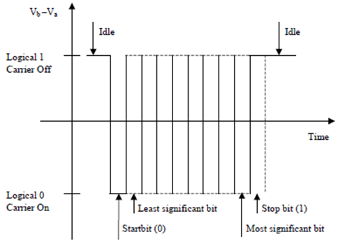
This option is constituted by a two wire bi-directional multi-drop configuration conforming to ISO/IEC 8482 [2]. The mapping of mark/space to logical one and zero as referred to in ISO/IEC 8482 [2] shall be according to Figure 4.1.1.
The use of ISB, also called idle-line failsafe in TIA/EIA TSB89 [3], is mandatory. The bias voltages shall be applied only by the primary device to any separate RS485 bus. The polarity of the idle-state bias is defined as a transmitted 1.
The RS485 transmitter shall be set to drive the bus before the first start bit is sent and held active until the last stop bit is sent. The RS485 transmitter shall stop driving the bus within 20 bit-times after the last stop bit is sent.
If an antenna modem is used ISB shall be implemented by the antenna modem.
![]()
![]()
![]()