Content for TS 32.260 Word version: 17.5.0
5.1.8 Charging support for roaming architecture for voice over IMS with local breakout
5.1.8A Charging support for roaming architecture for voice over IMS with home routed traffic
5.1.9 Charging support for Network provided Location information
5.1.9A Charging support for IMS transit scenarios
5.1.10 Charging support for TRF
5.1.11 Charging support for IMS service continuity
5.1.12 IMS support of announcements
5.1.13 Charging support of UE location(s) and TimeZone(s)
5.1.14 Charging support of duration based charging
...
...
5.1.8 Charging support for roaming architecture for voice over IMS with local breakout |R11| p. 26
The roaming architecture for voice over IMS with local breakout is described in the TS 23.228. The corresponding Charging principles are defined in the TS 32.240. In the present document, charging support for the Transit and Roaming Function (TRF) requisite for roaming architecture for voice over IMS with local breakout is rendered by presuming collocation or standalone.
Figure 5.1.8.1 shows an example for possible signalling and media flows in a roaming architecture for voice over IMS with local breakout.
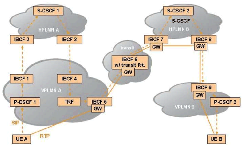
Figure 5.1.8.1: Signalling and media flows in a roaming architecture for voice over IMS with vocal breakout (example)
(⇒ copy of original 3GPP image)
(⇒ copy of original 3GPP image)
5.1.8A Charging support for roaming architecture for voice over IMS with home routed traffic |R14| p. 26
The charging principle of roaming architecture for voice over IMS with home routed traffic is described in TS 32.240.
In LBO roaming model where P-CSCF is located in VPLMN, the home network determines the serving PLMN of the UE from the location of the P-CSCF during initial IMS Registration, using the P-CSCF network identifier.
In deployments without IMS-level roaming interfaces where P-CSCF is located in HPLMN, the home network determines the serving PLMN of the UE using procedure defined in TS 23.228, where P-CSCF requests the PCRF/PCF to report the PLMN identifier where the UE is currently located. The received PLMN ID information is then forwarded in the SIP REGISTER request.Figure 5.1.8A.1 shows an example for possible signalling and media flows in a Roaming Architecture for Voice over IMS with home routed traffic.
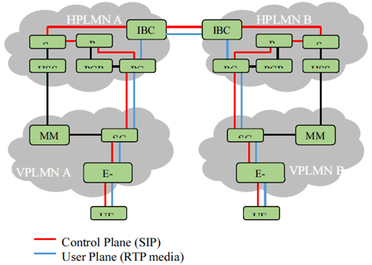
Figure 5.1.8A.1: Signalling and media flows in a Roaming Architecture for Voice over IMS with home routed traffic (Example)
(⇒ copy of original 3GPP image)
(⇒ copy of original 3GPP image)
5.1.9 Charging support for Network provided Location information |R11| p. 28
5.1.9.1 User location retrieval by IMS Nodes |R15| p. 28
The Network provided Location information (NetLoc) is described in the TS 23.228 and for emergency service request using PCC-based solutions for the UE location in mobile networks in TS 23.167.
In some scenarios, an AS can also detect emergency service and obtain the UE location using HSS-based solutions in TS 23.167.
Based on operator policies and the availability of the user location information and/or UE Time Zone from the access network, the solution ensures that relevant SIP messages contain the correct or up to date information about the user location information, and/or UE Time Zone provided by the access network and currently used by the UE.
For the 3GPP and non-3GPP accesses, the P-CSCF can retrieve user location information and/or UE Time Zone related to the access network currently used by the UE using PCC mechanisms, as specified in TS 23.203 , TS 23.503 and TS 29.214 . In some scenarios, an AS can also obtain location information using HSS-based solutions in TS 29.328.
For fixed networks, the P-CSCF is aware of the network provided location information through signalling with the NASS.
5.1.9.2 User location information content |R15| p. 28
As specified in clause 7.2A.4.3 of TS 24.229, the network provided location information is transported in the SIP P-Access-Network-Info header with an "np" parameter and indicates details of where the UE is currently located as defined in TS 23.228.
For trusted WLAN access, the SIP P-Access-Network-Info header includes the BSSID, and as specified in TS 23.228 Annex T, a Geographical Identifier, if generated by the P-CSCF or AS based on the retrieved Access Network Information.
For untrusted WLAN access, the SIP P-Access-Network-Info header includes the BSSID, and as specified in TS 23.228 Annex V, UE local IP address, ePDG IP Address, and the TCP source port or UDP source port used by the UE to establish the IKEv2 tunnel with the ePDG.
For 3GPP accesses, the SIP P-Access-Network-Info header includes the SAI, TAI, RAI, CGI, ECGI, and NCGI.
For other accesses, the SIP P-Access-Network-Info header includes specific user location information detailed in clause 7.2A.4.3 of TS 24.229.
5.1.9.3 User location Access charging |R15| p. 28
In the defined CDRs, the network provided location information available when the CDR is opened, for 3GPP accesses is directly available in the User Location Info field and also available in the Access Network Information or Additional Access Network Information fields. For non-3GPP accesses, the network provided location information available when the CDR is opened, shall be available in either the Access Network Information or Additional Access Network Information fields
5.1.9A Charging support for IMS transit scenarios |R12| p. 29
The IMS transit network scenarios are described in the TS 23.228 and may require additional functionalities provided by the IMS Transit Functions (TF). When residing in a stand-alone entity, the IMS TF may apply offline charging. Applicable fields for the IMS TF are in table 6.3.2.1.
5.1.10 Charging support for TRF |R11| p. 29
In order to support traffic for the Roaming Architecture for Voice over IMS with Local Breakout, IMS TF are enhanced with additional routing functionality, both combined in a Transit and Roaming Function (TRF and defined in TS 23.228. Depending on the transit operator configuration, these functions might reside in a stand-alone entity or be collocated with an existing IMS Network Element.
When residing in a stand-alone entity, the TRF may apply offline charging.
When collocated with an existing IMS Network Element, charging information for the TRF is combined with charging information of the corresponding IMS Network Element. Applicable fields are in table 6.3.2.1.
5.1.11 Charging support for IMS service continuity |R13| p. 29
The charging requirements for IMS service continuity using AS and ATCF are specified in TS 23.237.
Inter-UE transfer provides the capability of transferring the communication sessions with multiple media across different UEs and is part of Service Continuity (SC) as described in TS 23.237. For inter-UE transfer shall an AS implement the role of an SCC AS according to TS 24.337.
A complete session can be transferred from one UE to another with or without establishing a collaborative session as defined in TS 23.237 and TS 24.337. The SCC AS is able to serve an inter-UE transfer request initiated by the target UE without the establishment of a collaborative session regardless of the access technology used by either of the involved UEs.
For a consistent representation of the various access transfers specified in TS 23.237 and TS 24.337 in offline and online charging of the AS and in offline charging of the ATCF the Access Transfer Type parameter provides information on the used access technologies, e.g. PS to CS, CS to PS, PS to PS or CS to CS. The Inter-UE Transfer parameter indicates whether the access transfer was done between two UEs provided by the SCC AS as defined in TS 24.337. These parameters together, show the type of access transfer in detail, and are reported together with UE identification (i.e. Subscriber Equipment Number and/or Instance Id), Access Network Information and potentially Additional Access Network Information and Cellular Network Information available along the session transfer procedure.
Subsequently, the Requested Party Address parameter holds addresses related to session transfer if available: For SIP transactions, the address of the party (Public User ID or Public Service ID) to whom the SIP transaction was originally posted. For PS to CS transfer, the Session Transfer Number for Single Radio Voice Call Continuity (STN-SR) as described in TS 23.237. For CS to PS transfer, the Session Transfer Identifier for CS to PS Single Radio Voice Call Continuity (STI-SR) as described in TS 23.237.
5.1.12 IMS support of announcements |R13| p. 29
During a charging session, the CHF/OCS may utilize the Announcement service specified in TS 32.281 to request the IMS-GWF or AS to render video or audio announcements to a subscriber involved in an IMS session.
5.1.13 Charging support of UE location(s) and TimeZone(s) |R13| p. 29
As specified in clause 7.2A.4.3 of TS 24.229, and in RFC 7315, details of the UE location and Timezone are transported in the SIP P-Access-Network-Info header, which is conveyed in SIP signalling through IMS Nodes. Consequently UE location and TimeZone changes are addressed under SIP P-Access-Network-Info header changes.
The SIP P-Access-Network-Info header includes either UE-provided location, either Network-Provided location, both are subject to change independently during an IMS session. Any available UE-provided and Network-Provided locations are received by IMS Nodes in every SIP requests and responses, and transported in two P-Access-Network-Info headers when both are available.The charging support for Network-Provided location is described in clause 5.1.9.
As specified in clause 7.2.15.3 of TS 24.229, when a User Agent (UA) supporting one or more cellular radio access technology (e.g. E-UTRAN) is using a non-cellular IP-CAN to access the IM CN subsystem, details of the radio cell identity of the cellular radio access network on which the UE most recently camped are transported in the SIP Cellular-Network-Info header, which is conveyed in SIP signalling through IMS Nodes.
When Charging Data Request [Start/ Interim/Stop] are triggered for SIP session-related procedures, based on principles described in clause 5.2.1, any available SIP P-Access-Network-Info and SIP Cellular-Network-Info header(s) shall be reported to the CDF, using Access Network Information, Additional Access Network Information and Cellular Network Information IEs. The received IEs shall be included by the CDF:
- in Access Network Information, Additional Access Network Information and Cellular Network Information fields of IMS CDRs, upon Charging Data Request [Start] from IMS Nodes.
- in the List of Access Network Info Change field of IMS CDRs, upon reception of Charging Data Request [Interim, Stop] from IMS Nodes, only for SIP P-Access-Network-Info and SIP Cellular-Network-Info header(s) identified as changed.
5.1.14 Charging support of duration based charging |R16| p. 30
IMS Network Elements can not get the volume information from the underlying network as described in TS 24.229, therefore IMS charging only supports duration based charging.
![]()
![]()
![]()