Content for TS 32.101 Word version: 17.0.0
7.7 Software Management
7.8 Configuration Management
7.9 Accounting Management
7.10 Subscription Management
7.11 Subscriber and Equipment Trace Management
7.12 OAM&P of the PLMN "Management Infrastructure"
7.13 Service Level Trace Management
7.14 Management of QoE measurement collection
7.7 Software Management p. 45
7.7.1 Overview |R4| p. 45
This clause describes the software management process for 3rd Generation networks. Two main scenarios are considered:
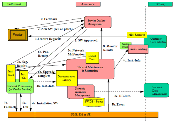
- Main Software Management process: It covers requesting, acceptance, installation, monitoring, documenting, database updating and feedback to the vendor for managing software. The sub-processes are valid for complete software releases and software patches for fault correction of the Network Elements and even element managers.
- Software Fault Management: Its emphasis is on network monitoring and handling faults, which are caused by software malfunctions.
7.7.1.1 Main Software Management process p. 45
The main focus is the management of new software releases and correction patches. Importance is placed integrating new software into a network with out causing unnecessary service disruptions and maintaining high levels of quality for the network. The main steps in the software management process are:
- Delivery of software from the vendor.
- Delivery of the software to local storage in the Network Elements and/or element managers.
- Validation of the software to ensure that the Software is not corrupt.
- Activation of the software to an executable state.
- Validation of the software to ensure that it runs correctly.
- Acceptance or rejection of the software, depending on the outcome of the validation. (A rejection of the software implies a reversion to a previous software version).
- Based on inputs from customer care interactions and marketing research, a network operator will establish new feature requirements. These requirements are sent to the vendor in the form of a feature request.
- The vendor delivers a new software release/correction with the corresponding documentation and installation procedure to the network operator. It should be noted that when a network operator utilises equipment from more than one vendor, this process runs as multiple parallel processes.
- A service quality management department of the network operator receives and reviews the software. Upon approving the software for installation, the software is sent to the network-provisioning department.
-
Installation Task:
- The software is installed in the appropriate Network Elements and/or element managers by network provisioning.
- Installation information is sent to the network maintenance and restoration department to inform them of pending changes in the network.
- Installation information is sent to the customer care centre to inform them of pending changes in the network.
-
Installation Test and Validation:
- Once the software has been installed, network provisioning performs tests to check and ensure that the new software is working properly.
- In addition to the checks that are performed by network provisioning, network maintenance and restoration could also detect malfunctions within and outside the updated Network Element (NE).
- Should network maintenance and restoration detect a problem within the updated Network Element (NE), then network provisioning is informed to decide on further actions.
-
Successful Installation Result:
- Upon successful installation of the software, the service quality management department is informed.
- A report is sent to network maintenance and restoration to inform them that the software will remain implemented in the network. At this point the documentation library and software database is updated.
- The network data management department is informed over the changes in the network.
-
Negative Installation Result:
- If the installation fails, network provisioning performs a "fallback", i.e. remove the new software and insure that the Network Element (NE) is running properly on the old software.
- A report containing the negative results and findings will be sent to service quality management and at the same time to network maintenance and restoration.
- Once the installation procedure has been ended, the network maintenance and restoration department closely monitors the affected Network Element (NE) to ensure proper performance.
- Service quality management will send feedback to the vendor as to the positive or negative results of the installation.

7.7.1.2 Software Fault Management p. 47
Software Fault Management involves the following steps:
- Detection of Software malfunctions in the network.
- Problem resolution. The origin of the malfunction is determined and corrective action is decided. The corrective action can be one of the following:
- Reversion to an earlier software version. This can imply both load and activation of the earlier software.
- Load and activation of correction software, according to clause 8.7.1.
- Re-activation of current software.
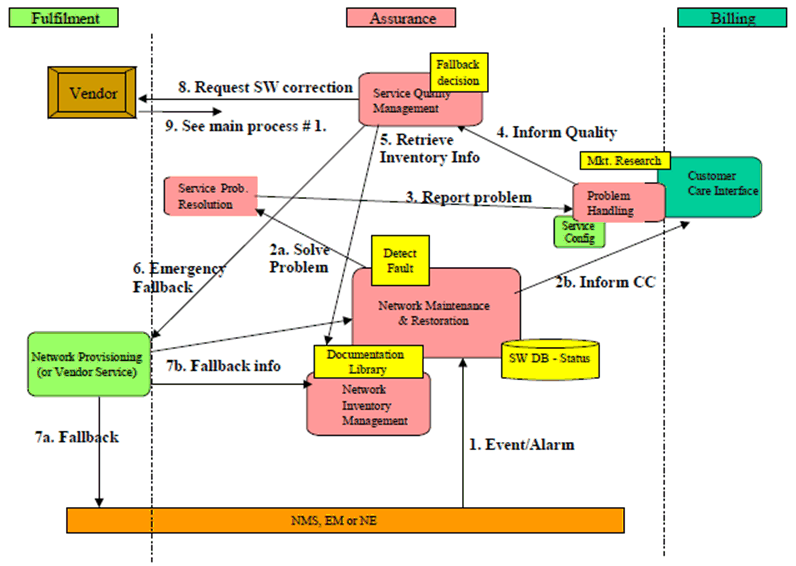
- The network maintenance and restoration department detects an event or an alarm/fault from the Network Element (NE).
-
Problem solving and informing customer care:
- The alarm is forwarded to the service problem resolution department for corrective actions and it is determined that the problem is caused by a software defect.
- In parallel the Customer Care Centre is informed, if the malfunction of the network may have impact on customers.
- The service problem resolution department informs problem handling and subsequently the customer care centre over service impairments with in the network.
- Problem handling reports to the service quality management department. The service disturbance is described within the report.
- Service quality management checks the current software level of the affected Network Element with the network inventory management department.
- If major network disturbances still appear the Service Quality management decides to fallback to a stable Software version (maybe some time after a new Software installation) and requests Network Provisioning.
- a+b): Network Provisioning performs the fallback and informs Network Maintenance and Inventory.
- Service quality management sends a request for a software correction to the vendor.
- The vendor sends a new software release or correction to the network operator. The rest of the procedure can be followed in the main software management process.

7.8 Configuration Management p. 49
A variety of components will make up an operator's actual implementation of a 3GPP system. Since it is an explicit goal of the standardisation effort within 3GPP to allow mix and match of equipment from different vendors, it is expected that many networks will indeed be composed of multiple vendors' equipment. For an operator to be able to properly manage this diverse network, in order to provide the quality of service expected by his customers, it is essential to standardise the Configuration Management for 3GPP systems at least to an extent that the operation of the multi-vendor network will be possible effectively and efficiently. Within the scope of Configuration Management, a distinction has to be made between those aspects targeting single Network Elements (NE management level) and those that are also, or exclusively, relevant for some part or the entire network (Network Management level).
Configuration Management is further specified in TS 32.600.
7.9 Accounting Management p. 49
3GPP charging data descriptions will be based on the requirements specified in TS 22.115 "Service aspects; Charging and Billing" and on the charging principles outlined in TS 32.200 "Charging management; Charging Principles" [55]. The main content of 3GPP charging data descriptions will be:
- Layout and formats of Charging Data Records (CDRs) for the 3GPP core network nodes (circuit, packet switched and IP Multimedia) and service nodes (e.g. MMS);
- Data generation dependent on call states, chargeable events and TS 22.115 service requirements;
- Formal description of the CDRs format in ASN.1 (ITU-T Recommendation X.680-1997 [49]) and definition of a file transfer mechanism (FTP).
7.10 Subscription Management p. 50
Subscription Management (SuM) is a feature that permits Service Providers, Value Added Service Providers and Mobile Operators to provision services for a specific subscriber. The feature is necessary to allow Service Providers and Operators to provision, control, monitor and bill the configuration of services that they offer to their subscribers. SuM focuses on the OAM processes to manage subscription information. These correspond to the 'Fulfilment' Process areas of the TeleManagement Forum Telecom Operations Map [100].
SuM is an area of service operation management that sets a complex challenge for Service Providers and Operators in their support of new or existing subscribers during their every day network operation.
In GSM solutions the main repository of the subscription information is in the Home Locations Register (HLR). However the management and administration interfaces for controlling this information is proprietary to each vendor. The use of proprietary interfaces is inconvenient for those Operators using multiple vendors' equipment since their provisioning systems have to accommodate multiple proprietary interfaces, which perform essentially identical functions. Moreover, it makes it more difficult to generate customer self care applications that allow subscribers to provision, and amend subscription data.
The 3GPP environment requires more complex service delivery mechanisms than in GSM and SuM is no longer simply an internal matter for a single operator but a capability that is achieved by linking together features across multiple Service Providers and Operators Operations Support Systems (OSS). Historically, the services provided by Operators have been defined within standards groups such as ETSI or 3GPP. With the advent of Open Services Access (OSA) being adopted by 3GPP the User Service Definitions will be replaced by Service Capabilities traded amongst Service Providers and Network Operators. This will allow Operators and Service Providers to define customized service environments that roam with users as they move amongst networks - this is the Virtual Home Environment (VHE) TR 22.121. This customized service environment means that subscription information is held in a number of locations including the Home Network, the Visited Network, the User Equipment, Application VASP Equipment (e.g. servers accessed by the subscriber for content and information based services) and the Operations Systems of the Service Providers, and Operators supporting the subscriber's service subscription.
Service delivery and support across multiple vendors' solutions and organizations is a feature of other industries, and the solutions adopted are secure supply chain solutions based upon mainstream e-commerce principles, methods and technologies.
There is a relationship between this feature and the PS Domain, CS Domain, IP Multimedia Subsystem (IMS), Authentication Center (AuC), Open Services Access (OSA) and Generic User Profile (GUP) documented in other 3GPP specifications.
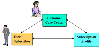
The conceptual model for SuM is illustrated in Figure 10.

SuM is concerned with provisioning the subscription profile throughout all the systems and trading partners needed to realize the customer service, SuM provides specifications that define the interfaces and the procedures that interconnect the three points of the SuM triangle: Customer Care Center, the User and the network (s) where the Subscription profile resides (such as HSS, USIM, etc.).
The SuM requirements are described in more detail in TS 32.140, The SUM Architecture is described in TS 32.141.
7.11 Subscriber and Equipment Trace Management |R5| p. 51
Subscriber and Equipment Trace Management is a Feature that allows a Network Operator to activate/deactivate from the Network Management system the tracing of a particular subscriber within the network. Once activated the trace activity is reported back to the Network Management system. It will be possible to request activation of a trace from different Network Elements (via the appropriate Element Management Functionality) depending on the operator's requirements.
7.12 OAM&P of the PLMN "Management Infrastructure" |R5| p. 51
As described earlier in the present document, each PLMN organisation has a management infrastructure consisting of a collection of systems (computers and telecommunications) - a TMN in ITU-T parlance - used to manage its network. Though this management network is logically distinct from the PLMN , the operations systems and supporting data communications network comprising it have the same management needs as described for network elements and where possible should be managed using the same principles and similar management processes and functionality.
7.13 Service Level Trace Management |R12| p. 51
Service Level Trace Management is a feature that allows a Network Operator to activate/deactivate from the Network Management system the tracing of a particular subscriber and the service that they are consuming within and across an IP Multimedia Subsystem (IMS). Once activated the trace activity is reported back to the Network Management system. It is possible to request activation of a trace from different Network Elements including the UE (via the appropriate Element Management Functionality) depending on the operator's requirements.
The activation/deactivation and reporting interface for Trace Management between the Network Management and Element Management Systems is specified in the Trace IRP.
7.14 Management of QoE measurement collection |R16| p. 51
Management of QoE measurement collection is a feature that allows a network operator to activate/deactivate from the network management system the collection of QoE information (DASH or MTSI) from applications that are consumed in the UE. When the application has recorded QoE information, it is sent to a specified destination. It is possible to request activation of QMC from an specified area in the network.
The activation/deactivation and reporting interface for the QMC between the network management and element management systems is specified in the Management of Quality of Experience (QoE) measurement collection IRP.