Content for TS 24.010 Word version: 18.0.0
5 Supplementary service cross phase compatibility
5.1 Cross phase, or cross protocol version, interworking
5.2 Objectives
5.3 Supplementary service compatibility philosophy
5.4 Compatibility mechanisms
5.5 SS compatibility procedures
5.6 Development of future protocol versions
6 Forward Check SS Indication
A Notation used for stage 3 description of supplementary services
A.1 General structure of the SS stage 3 diagrams
A.2 Messages used to transport operations
A.3 Contents of messages
$ Change history
5 Supplementary service cross phase compatibility p. 23
5.1 Cross phase, or cross protocol version, interworking p. 23
Due to the phased approach to GSM standardisation it is possible for a service to be changed, or new services to be added, between different versions of the standard. Since GSM supports the features "terminal mobility" and "roaming" and is a system of open interfaces, it is possible for entities supporting different versions of the standards to have to interwork. This clause describes the supplementary service procedures which provide this interworking.
This clause describes compatibility procedures for radio interface SS operations. In this clause the term "SS operation" refers to one of the operations sent in the Facility IE as defined in TS 24.080 and TS 29.002. An "MS initiated operation" is an SS operation where the MS sends the invoke component. A corresponding definition applies to network initiated operations.
5.2 Objectives p. 23
The objectives of these procedures are as follows:
- to allow flexibility of implementation, i.e. allow different combinations of services to be supported at different versions within a single entity;
- to allow SSs to evolve from version to version of the standards;
- to decouple SS protocol from other protocols;
- to guarantee the best quality of service in situations where different entities support different versions of that service.
5.3 Supplementary service compatibility philosophy p. 23
The purpose of the SS compatibility procedures is to ensure that when a service is invoked the highest common version of the service protocol is used in the entities supporting that service. The highest protocol version gives the best level of service to the subscriber. The commonality of versions between entities provides compatibility.
The basic philosophy is that the MS shall provide the network with information about its capabilities in order that the network may adjust to the capabilities of the MS. This ensures that compatible information is sent to the MS. This process is not required in the other direction, i.e. the network does not provide the MS with capability information. The network is expected to be able to cope with unexpected information cleanly and due to network evolution will generally be more advanced than operating MSs.
In this description the terms "phase" and "version" are used with respect to supplementary services. In this context "phase" means a particular collection of GSM standards or an implementation according to that phase of standards. In each phase of GSM standards "versions" of a service or protocol are described. Therefore it is sometimes applicable to refer to which version of a service is supported.
5.4 Compatibility mechanisms p. 24
Two signalling indicators are used in the MS to network direction to provide information on the general capabilities of the MS and on specific SS protocol versions. A protocol extension mechanism is also used for protocol evolution.
5.4.1 SS screening indicator p. 24
The SS screening indicator is sent by the MS at the beginning of the radio connection to allow the network to assess the capabilities of the MS and hence determine,
- whether a particular network initiated SS operation may be invoked; or
- what version of a network initiated SS operation should be invoked.
5.4.2 SS version indicator p. 24
The SS version indicator is sent by the MS and is associated with one or more related SS operations. It indicates to the network the correct version of radio interface protocol and procedures to use for those SS operations. For call related SSs the version indicator is valid for the invocation period of the SS operation to which it was attached (i.e. the validity of the invoke ID). For call independent SSs the indicator is valid for the duration of the call independent transaction. The SS version indicator takes precedence over the screening indicator during its period of validity. The coding of the SS version indicator is described in TS 24.008 and TS 24.080.
5.4.3 Protocol extension mechanism p. 24
A protocol extension mechanism is used in the common information element category supplementary service protocol to allow controlled evolution of the protocol. The purpose of this mechanism is to allow optional information to be introduced into operations without causing receiving entities, who do not recognise this information, to reject the entire operation.
5.5 SS compatibility procedures p. 24
5.5.1 Screening indicator procedures p. 24
5.5.1.1 MS procedure p. 24
If a MS supports Phase 2 3GPP TS 24.010 error handling and the Phase 2 TS 24.080 extension mechanism it shall send the screening indicator to the network during layer 3 connection establishment. The value of the indicator shall indicate Phase 2. The sending of the screening indicator does not depend upon the invocation of any supplementary service.
5.5.1.2 Network procedure p. 25
At layer 3 connection establishment with the MS, the network shall check for the SS screening indicator and note, for the duration of the connection, whether the indicator was sent, and if sent, the value of the indicator.
On invocation of any network initiated SS operation (unless an SS version indicator has taken precedence over the screening indicator) the network shall check the screening indicator status. If the screening indicator was not sent, the network shall screen information sent to the MS, i.e. invoke the Phase 1 version of the operation or abort the invocation if only a Phase 2 version is available. If the screening indicator was received, indicating that Phase 2 error handling and extension mechanisms are supported at the MS, the network shall invoke the highest supported version of the operation toward the MS.
According to this version of the standards the highest version is Phase 2. However when the next version of standards is available, new services may also be invoked. If the MS does not support the service the error handling or extension mechanism will handle unrecognised information cleanly.
If in the future a new value is assigned to the screening indicator, new screening procedures may also be defined for networks of similar or higher capability. These procedures cannot be predicted and no definition is required in this version of the standards.
If the value of the screening indicator is unrecognised the network shall attempt to handle network initiated SS operations as if the MS had indicated the highest values supported by the network.
The indicator has been defined in such a way that it is ignored when received by a Phase 1 network therefore no Phase 1 procedures are described.
5.5.2 SS version indicator procedures p. 25
5.5.2.1 MS procedure p. 25
If an SS operation has been initiated at the MS, and the MS supports Phase 2 3GPP TS 24.010 error handling and the Phase 2 TS 24.080 extension mechanism and the operations used by the mobile initiated procedure are implemented according to the Phase 2 GSM standards, then:
- in the case of call independent activity, the MS shall send the SS version indicator at the beginning of the transaction indicating the version of the SS operation being invoked. No further indication shall be sent by the MS during the transaction. No operations shall be sent within the same transaction which are not compliant with the SS version indicated.
- in the case of call related activity, the MS shall send the SS version indicator in the TS 24.008 message containing the invoke component of the related operation. The version of the service being invoked is indicated. This procedure applies on a per operation basis and shall be repeated for each call related operation.
5.5.2.1.1 MS procedure for version 3 or higher operations p. 25
The relevant stage 3 specification for each service shall state if the operation requires the use of SS version 3 or higher for MS initiated operations.
The SS version indicator is used within the network to define the MAP Application Context used for a specific operation (see TS 29.002). An MS initiating an SS version 3 or higher operation must be able to decode all of the possible returned information from the MAP Version 3 Application Context of the operation invoked.
If an SS version 3 or higher operation has been initiated at the MS, then:
- in the case of call independent activity, the MS shall send the SS version 3 or higher indicator at the beginning of the transaction indicating the version of the SS operation being invoked. No further indication shall be sent by the MS during the transaction. No operations shall be sent within the same transaction which are not compliant with the SS version indicated.
- in the case of call related activity, the MS shall send the SS version 3 or higher indicator in the TS 24.008 message containing the invoke component of the related operation. The version of the service being invoked is indicated. This procedure applies on a per operation basis and shall be repeated for each call related operation.
5.5.2.2 Network procedure p. 26
5.5.2.2.1 Call independent SS activity p. 26
When a new transaction is set up for call independent SS activity the network shall check for the SS version indicator and note, for the duration of the transaction, whether the indicator was present, and if present, the value of the indicator.
The network shall use this indication to establish the correct MAP application context in the network for the processing of all operations made on that transaction. The network shall discard this information at the end of the transaction. If the indicator was not present the network shall operate according to Phase 1. If the indicator was present and indicates Phase 2 the network shall operate according to the Phase 2 standards. If the value of the indicator is unrecognised the network shall attempt to handle the communication at its highest possible version. The detailed interworking for this situation is described in subclause 5.5.4.
The screening indicator shall not be taken into account for processing transactions that start with MS initiated operations.
Special procedures concerning SS version indicator values other than Phase 2 will be described in future standards if required.
5.5.2.2.2 Call related SS activity p. 26
When a call related common information element SS operation is received by the network, the network shall check the TS 24.008 carrier message for the SS version indicator. The network shall note whether the indicator was present, and if present, what value was provided.
The network shall use this information to operate in a compatible way and set up compatible contexts in the fixed network. If the indicator was not present the network shall operate according to Phase 1. If the indicator was present and indicates Phase 2 the network shall operate according to the Phase 2 standards. If the value of the indicator is unrecognised the network shall attempt to handle the communication at its highest possible version.
The network shall discard the indicated information when the operation has been completed, i.e. when a result, error or reject is provided. If no response is expected to an operation the indicator is discarded immediately after the operation has been processed.
The screening indicator shall not be taken into account for processing MS initiated operations.
If the version indicator is received but no supplementary service information is supplied the network shall ignore the indicator.
Special procedures concerning SS version indicator values other than Phase 2 will be described in future versions of the standards if required.
5.5.3 Extension mechanism procedures p. 26
The handling of the extension mechanism (ellipsis) is a detailed protocol matter and is described in the MAP version 2, TS 29.002.
5.5.4 SS version indicator - MAP context interworking p. 26
5.5.4.1 Call independent interworking p. 26
The compatibility mechanisms described in these subclauses concern the radio interface. The fixed network protocol MAP also specifies compatibility mechanisms. The interworking between these mechanisms occurs at the MSC/VLR.
The MSC shall operate and set up contexts according to the version indicated by the MS wherever possible. If the MS signals a higher version than the MSC/VLR is capable of supporting, the MSC/VLR shall attempt to support service at the highest version which is supported. If this is not possible then the communication is rejected.
Detailed interworking is described in TS 29.011.
5.5.4.2 Call related interworking p. 27
No interworking identified.
5.6 Development of future protocol versions p. 27
As a general rule all future versions of protocol should be designed such that they are a superset of the previous protocol. This provides backward compatibility.
Optional information shall be introduced, where appropriate, in the extensible parts of operations.
Non-compatible protocol changes, i.e. the introduction of mandatory protocol elements or new operations shall cause an increment in the protocol version. This shall be reflected in the use of the SS version indicator. Amendments to the Phase 2 services shall specify in the relevant stage 3 specification which value of the SS version indicator to use for MS initiated operations.
The extension mechanism shall be introduced wherever possible in new operations or new constructed data types of the common information element SS protocol.
Care should also be taken that functional service changes are made in a backwards compatible manner.
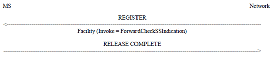
6 Forward Check SS Indication p. 27
The forward check SS indication procedure is used when supplementary services data in the HLR may have become corrupted. The procedure is initiated by the network to inform the user to verify his supplementary services data. The procedure consists of the network sending the ForwardCheckSSIndication operation on a call independent SS transaction. The procedure shall create a new network initiated transaction.
The new transaction may be used on its own, or in parallel with other call independent SS transactions. The message flow is shown in Figure 6.1.
A (Normative) Notation used for stage 3 description of supplementary services p. 28
The structure of the signalling used for supplementary services on the Um Interface is defined using diagrams in 3GPP TS 24.010 and the 3GPP TS 24.08x and 24.09x-series of technical specifications. These SS stage 3 diagrams show example message flows between the MS and the network.
Separate diagrams specify how supplementary services signalling shall be used to perform each defined supplementary service function. For signalling that uses the common information element approach, these diagrams are the normative definition of a number of important aspects of the supplementary services signalling:
- the diagrams normatively define the allowed responses to each supplementary service operation shown;
- the diagrams normatively define which TS 24.008 or TS 24.080 message is to be used to transport the supplementary services operations in the Facility IE;
- The diagrams normatively define which parameters are allowed and required in the invocation and response of each operation.
A.1 General structure of the SS stage 3 diagrams p. 28
In the SS stage 3 diagrams the messages that correspond to the normal case with successful outcome are shown using solid arrows. Messages for exceptional, or unsuccessful cases are shown using dashed arrows. In general, the diagrams show the initiating operation together with all possible outcomes. Obviously, in practice only one of the possible outcomes shown in the diagrams will occur when the operation is used. An example is given in Figure A.1.
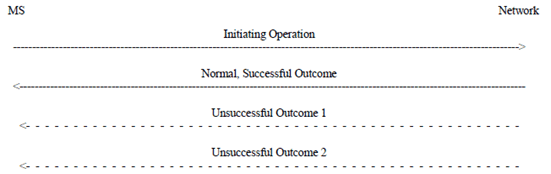
Figure A.1: Example of the general structure of the SS stage 3 diagrams
(⇒ copy of original 3GPP image)
(⇒ copy of original 3GPP image)
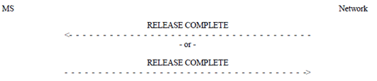
A.1.1 Exceptional release procedures p. 29
To prevent transactions being kept open following exceptional cases, either side of the transaction may release it by sending a RELEASE COMPETE message without a Facility IE. This procedure can be used to release any call independent SS procedure, at any time while supplementary service support is established. For clarity this is not shown on the specific diagrams in the 3GPP TS 24.08x and 24.09x series, though it is still available.
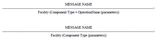
A.2 Messages used to transport operations p. 29
The message used to transport the supplementary service operation is shown above the arrow. If a single message or a list of messages is specified then only these messages shall be used to transport the operation shown in the context shown. If the letters "e.g." are included before the message name or a list of messages then the messages shown are only suggested examples. If "e.g." is used then any message that carries the Facility information element which is consistent with the transaction state may be used for the SS operation.
A.3 Contents of messages p. 29
The contents of messages is specified below the arrow. The diagrams do not show the SS version indicator, or other parts of the message contents unless they are directly related to the service shown. The names of relevant information elements are shown, and the associated contents is shown in brackets.
If the information element is the Facility IE then the contents information includes:
- the type of component that shall be used for the operation (e.g. invoke, return result, return error, reject);
- the name of the operation to be used (for the invoke and return result components only);
- the parameters that shall be included in the operation. For the function described by the diagram, only those parameters shown in the diagram are allowed. Unless stated otherwise all the parameters shown in the diagram shall be present when the operation is used for the function described by the diagram.
$ Change history p. 31
![]()
![]()