Content for TS 23.283 Word version: 18.1.0
1…
10…
10.2…
10.2.2…
10.2.3…
10.3…
10.3.3…
10.3.3.7…
10.3.4…
10.3.4.4…
10.3.5…
10.3.5.8…
10.3.6…
10.3.7…
10.3.7.5…
10.3.8…
10.4…
10.4.4…
10.5…
10.5.7…
10.6…
10.6.2…
10.6.2.3…
10.6.3…
10.6.4…
10.7…
10.8…
10.11…
10.11.4…
10.12…
10.14…
10.15…
10.5.7 Floor control without local filtering on an interworking group defined in the LMR system
10.5.8 Floor control without local filtering on an interworking group defined in the MCPTT system
10.5.9 Floor control in private call controlled by the LMR system
10.5.10 Floor control in private call controlled by the MCPTT system
...
...
10.5.7 Floor control without local filtering on an interworking group defined in the LMR system p. 111
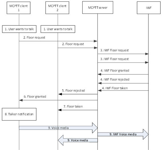
Figure 10.5.7-1 shows the procedure for floor control on an interworking group defined in the LMR system where local filtering is not performed by the MCPTT server. Simultaneous floor requests are included to show various aspects of interworking floor control.
Pre-conditions:
- The interworking group is defined in the LMR system.
- The MCPTT system is configured to send competing floor control requests to the LMR system (represented by the IWF) for floor control arbitration.
- MCPTT client 1, MCPTT client 2, and LMR users are affiliated to that group.
- An interworking group call is ongoing involving MCPTT users and LMR users. The floor is currently idle.

Figure 10.5.7-1: Floor control without local filtering on a group defined in the LMR system
(⇒ copy of original 3GPP image)
(⇒ copy of original 3GPP image)
Step 1.
The users of MCPTT client 1 and MCPTT client 2 both want to send voice media over the session.
Step 2.
MCPTT clients 1 and 2 send floor request messages to the MCPTT floor control server.
Step 3.
Since the group is defined in the LMR system the MCPTT floor control server forwards these floor requests to the IWF for final floor control determination. The IWF performs floor arbitration in conjunction with the LMR system (not shown). The IWF determines that the floor can be granted to MCPTT client 1.
Step 4.
The IWF sends an IWF floor granted message for MCPTT client 1, an IWF floor rejected message for MCPTT client 2, and an IWF floor taken message for MCPTT client 2 to the MCPTT floor control server.
Step 5.
The MCPTT floor control server sends a Floor rejected message to MCPTT client 2 to notify the user that his/her floor request was rejected.
Step 6.
The MCPTT floor control server sends a Floor granted message to MCPTT client 1.
Step 7.
The MCPTT floor control server sends a Floor taken message to MCPTT client 2 to notify the user of who is granted the floor.
Step 8.
MCPTT client 1 notifies the user that he/she has been granted the floor and may begin speaking.
Step 9.
MCPTT client 1 begins sending voice media over the established session. The media is distributed to affiliated group members including the IWF.
10.5.8 Floor control without local filtering on an interworking group defined in the MCPTT system p. 113
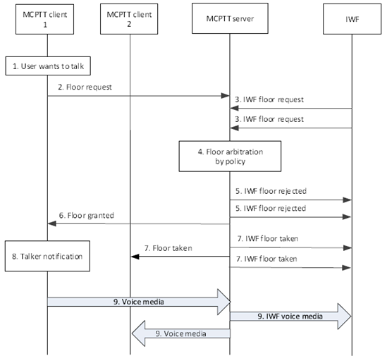
Figure 10.5.8-1 shows the procedure for floor control on an interworking group defined in the MCPTT system where local filtering is not performed by the LMR system. Simultaneous floor requests are included to show various aspects of interworking floor control.
Pre-conditions:
- The interworking group is defined in the MCPTT system.
- MCPTT client 1, MCPTT client 2, and LMR users are affiliated to that group.
- The LMR system (represented by the IWF) is configured to send all competing floor control requests to the MCPTT system for floor control arbitration.
- The IWF is not affiliating on behalf of LMR users. All LMR group affiliations are passed through the IWF to the MCPTT server.
- An interworking group call is ongoing involving MCPTT users and LMR users. The floor is currently idle.

Figure 10.5.8-1: Floor control without local filtering on a group defined in the MCPTT system
(⇒ copy of original 3GPP image)
(⇒ copy of original 3GPP image)
Step 1.
The user of MCPTT client 1 wants to send voice media over the session. At the same time multiple users in the LMR system (represented by the IWF) want to also send voice media over the session.
Step 2.
MCPTT client 1 sends a floor request message to the MCPTT floor control server.
Step 3.
The IWF sends floor request messages to the MCPTT floor control server for each LMR user requesting the floor. In this case two LMR users are requesting the floor. These floor requests contain the MCPTT ID of the LMR user (converted by the IWF).
Step 4.
Since the group is defined in the MCPTT system the MCPTT floor control server performs final floor control determination. In this case the MCPTT floor control server determines to accept the floor request from MCPTT client 1 based on local policy and arbitration results (e.g., according to priority of the request versus the competing requests from the IWF).
Step 5.
The IWF is notified that its floor requests were rejected. The MCPTT floor control server sends an IWF floor rejected message to the IWF for each floor request.
Step 6.
The MCPTT floor control server sends a floor granted message to MCPTT client 1.
Step 7.
The MCPTT floor control server sends floor taken messages to MCPTT client 2 and the IWF to inform them of who is granted the floor. In this case a floor taken message is sent to the IWF corresponding to each affiliated LMR user.
Step 8.
MCPTT client 1 notifies the user that he/she has been granted the floor and may begin speaking.
Step 9.
MCPTT client 1 begins sending voice media over the established session. The media is distributed to affiliated group members including the LMR users.
10.5.9 Floor control in private call controlled by the LMR system |R16| p. 114
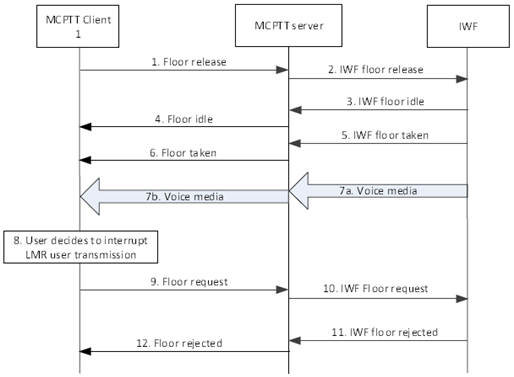
Figure 10.5.9-1 shows a procedure for a private call with floor control where the LMR system controls the floor. A request for transmission by the MCPTT user while the LMR user has the floor is rejected by the IWF, to show various aspects of interworking floor control.
Pre-conditions:
- A private call has been set up between an LMR user and MCPTT client 1.
- The LMR system is controlling the floor, via the IWF.
- MCPTT client 1 has the floor.

Step 1.
The user of MCPTT Client 1 finishes transmission and MCPTT client 1 releases the floor.
Step 2.
The MCPTT server informs the IWF of the floor release.
Step 3.
The IWF indicates that the floor is now idle.
Step 4.
MCPTT client 1 is informed that the floor is idle.
Step 5.
The IWF indicates that the floor has been taken by the LMR user.
Step 6.
The MCPTT server informs MCPTT client 1 that the floor has been taken by the LMR user.
Step 7.
Media flows from the LMR user to the IWF (7a) and on to MCPTT client 1 (7b).
Step 8.
The user of MCPTT client 1 decides to interrupt the transmission from the LMR user.
Step 9.
MCPTT Client 1 sends a floor request with an appropriate priority to request interruption of the transmission from the LMR user.
Step 10.
The MCPTT server forwards the floor request to the IWF.
Step 11.
The LMR system rejects the request, and the IWF informs the MCPTT server of the rejection.
Step 12.
The MCPTT server informs MCPTT client 1 that the request for interruption has been rejected.
10.5.10 Floor control in private call controlled by the MCPTT system |R16| p. 115
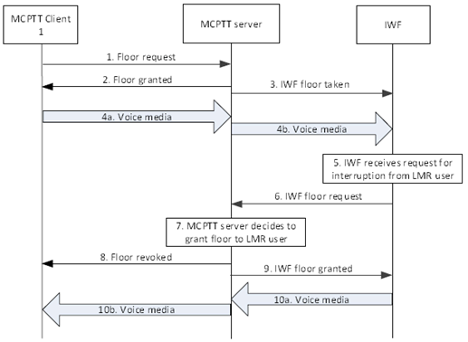
Figure 10.5.10-1 shows a procedure for a private call with floor control where the MCPTT system controls the floor. A request for transmission by the LMR user while the MCPTT user has the floor is accepted by the MCPTT server, to show various aspects of interworking floor control.
Pre-conditions:
- A private call has been set up between the LMR user and MCPTT client 1.
- The MCPTT server is controlling the floor.
- The floor is idle.

Step 1.
MCPTT Client 1 requests the floor.
Step 2.
The MCPTT server grants the floor to MCPTT Client 1.
Step 3.
The MCPTT server informs the IWF that the floor has been granted to MCPTT client 1.
Step 4.
MCPTT client 1 sends voice media to the MCPTT server (4a) which forwards the voice media to the IWF (4b).
Step 5.
The LMR user decides to interrupt the transmission from MCPTT client 1, and the IWF is informed.
Step 6.
The IWF sends a floor request to the MCPTT server with sufficient priority to interrupt MCPTT client 1.
Step 7.
The MCPTT server decides to allow the interruption from the LMR user, based on the priority of the request and on configuration.
Step 8.
The MCPTT server informs MCPTT Client 1 that the transmission permission has been revoked.
Step 9.
The floor is granted to the LMR user via the IWF.
Step 10.
Voice media is sent from the LMR user via the IWF to the MCPTT server (10a) and on to MCPTT client 1 (10b).