Content for TS 23.261 Word version: 17.0.0
5.3 Addition of an access to a PDN connection
5.3.1 General
5.3.2 Addition of WLAN access
5.3.3 Addition of 3GPP access
...
...
5.3 Addition of an access to a PDN connection p. 11
5.3.1 General p. 11
This clause specifies the additional procedures for adding an access to an existing PDN connection over a 3GPP access or a WLAN access when the UE supports IP flow mobility. In these flows it is assumed that the UE has performed a PDN Connection establishment procedure through one access as specified in clause 5.2. Subsequently the UE attaches to a second access and starts using both accesses for the same PDN connection. As a result the UE is simultaneously connected via both accesses and a set of traffic flows are routed through one access while the remaining traffic flows are routed through the other access.
Non-roaming, home routed roaming and Local Breakout cases are supported by this procedure. The AAA proxy and vPCRF are only used in the case of home routed roaming and Local Breakout. In non-roaming scenarios, the AAA proxy and vPCRF are not involved.
The optional interaction steps between the gateways and the PCRF in the procedures only occur if dynamic policy provisioning is deployed in EPC. These steps are never present when the solution is applied to I-WLAN mobility architecture according to TS 23.327.
5.3.2 Addition of WLAN access p. 12
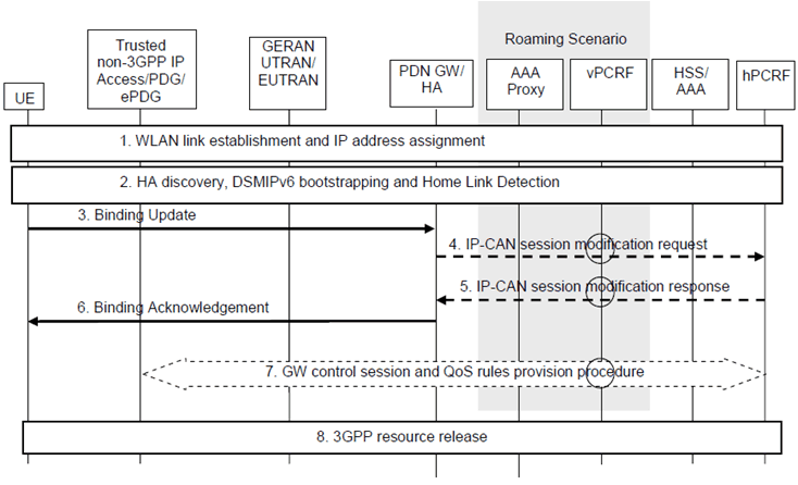
After successfully attachment to 3GPP access, the UE has established a PDN connection over 3GPP access as specified in clause 5.2.2. Subsequently the UE performs the WLAN attachment, and requests to establish a PDN connection using the same APN, and attempts to use both accesses for the same PDN connection simultaneously. The WLAN access may be considered as the UE's foreign link from DSMIPv6 perspective.

The signalling flow above shows the particular case where the UE is first connected to a 3GPP access and then it requests addition of a WLAN access.
Step 1.
The UE discovers a WLAN and connects to it and configures an IPv4 address and/or an IPv6 address/prefix according to TS 23.402 or TS 23.327, depending whether the WLAN access is used in the context of EPC or I-WLAN mobility architecture.
Step 2.
The UE performs HA discovery, DSMIPv6 bootstrapping and DSMIPv6 home link detection procedure according to TS 23.402 unless already performed in the 3GPP access.
Step 3.
The UE sends a DSMIPv6 Binding Update (HoA, CoA, Lifetime, BID, FID, flow description) message to the HA over the WLAN access. The UE may include the requested routing rules via the FID mobility option with both the routing filters and the BID (which includes the routing address) as specified in RFC 5555, RFC 5648 and RFC 6089. The UE can include more than one routing rule by including multiple FID mobility options in the Binding Update. The DSMIPv6 Binding Update also contains an indication which indicates that the home link (3GPP access) is still connected and also the BID mobility options which identify that one binding is associated with the home address (3GPP access) and the other with the Care-of-Address from the WLAN access. The UE also indicates in the Binding Update which is the default binding where the HA should route packets not matching any FID as specified in RFC 6089.
Step 4.
In case the HA function is located in the PDN GW and dynamic PCC is deployed, the PDN GW sends an IP-CAN session modification request to the PCRF. In this request, the PDN GW provides the updated routing rules to the PCRF. The PCRF stores the mapping between each SDF and its routing address.
Step 5.
If the HA function is located in the PDN GW, based on the successful establishment of resources at the BBERF, the PCRF sends an acknowledgement to the PDN GW, including updated PCC rules if appropriate.
Step 6.
The HA creates a DSMIPv6 binding, installs the IP flow routing rules and sends a Binding Acknowledgment (Lifetime, HoA, CoA, BID, FID) as specified in RFC 5555, RFC 5648 and RFC 6089, to indicate which routing rules requested by the UE are accepted.
The PDN GW may send message 6 before receiving the reply from PCRF in message 5.
Step 7.
Based on the IP-CAN session modification request (if step 4 was performed), the PCRF ensures that the relevant QoS rules for the SDFs are installed in the target BBERF. This is done by a GW control session and QoS rules provision procedure as specified in TS 23.203.
Step 8.
In case the HA function is located in the PDN GW, appropriate 3GPP resource release procedures are executed for the resources associated with the flows that were moved away from the 3GPP source access. This procedure may be triggered by the PCRF via a GW control session and QoS rules provision procedure if PMIPv6 is used on S5 and it may be triggered by the PDN GW in case GTP is used on S5.
If the HA function is implemented in I-WLAN mobility, the UE may initiate GPRS resource release procedures for those resources that were moved away from the 3GPP source access, as specified in TS 23.060.
5.3.3 Addition of 3GPP access p. 13
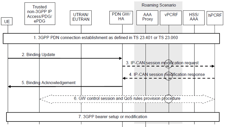
After successfully attachment to WLAN access, the UE has established a PDN connection over WLAN as specified in clause 5.2.3. As the UE detected the WLAN access is not the home link from DSMIPv6 perspective, DSMIPv6 signalling was triggered over the WLAN access.
Subsequently, as described in this clause, the UE performs the initial attachment procedure or PDN Connection establishment procedure over a 3GPP access and establishes a PDN connection using the same APN, as described in TS 23.060, TS 23.401 or TS 23.402. As the UE has indicated IP flow mobility during the initial attachment over WLAN, the 3GPP access attachment completion shall not trigger the DSMIPv6 binding deregistration.

The signalling flow above shows the particular case where the UE is first connected to a WLAN access and then it requests addition of a 3GPP access.
Step 1.
The UE discovers a 3GPP access and performs the Attach or PDN Connection establishment procedure according to TS 23.401 or TS 23.060. Specifically, the UE sets the Request Type to Handover to facilitate the MME selects the same PDN GW/HA as the UE connects in WLAN Access. Since the UE has indicated IP flow mobility support during the initial attachment over WLAN, the HA shall not deregister the DSMIPv6 binding by sending a Binding Revocation Indication towards the WLAN access.
Step 2.
The UE sends a DSMIPv6 Binding Update (HoA, CoA, Lifetime, BID, FID, flow description) message to the HA over the 3GPP access. The UE may include the requested routing rules via the FID mobility option with both the routing filters and the BID (which includes the routing address) as specified in RFC 5555, RFC 5648 and RFC 6089. If the 3GPP access is the home link, the UE sets the 'H' flag in the respective BID mobility option, as specified in RFC 6089. The UE can include more than one routing rule by including multiple FID mobility options in the Binding Update. The UE also indicates in the Binding Update which is the default binding where the HA should route packets not matching any FID as specified in RFC 6089.
Step 3.
In case the HA function is located in the PDN GW and dynamic PCC is deployed, the PDN GW sends an IP-CAN session modification request to the PCRF. In this request, the PDN GW provides the updated routing rules to the PCRF. The PCRF stores the mapping between each SDF and its routing address.
Step 4.
If the HA function is located in the PDN GW, based on the successful establishment of resources at the BBERF, the PCRF sends an acknowledgement to the PDN GW, including updated PCC rules if appropriate.
Step 5.
The HA sends a Binding Acknowledgment (Lifetime, HoA, CoA, BID, FID) as specified in RFC 5555, RFC 5648 and RFC 6089, to indicate which routing rules requested by the UE are accepted.
The PDN GW/HA may send message 5 before receiving the reply from PCRF in message 4.
Step 6.
Based on the IP-CAN session modification request (if step 3 was performed), the PCRF ensures that the relevant QoS rules for the SDFs are installed in the target BBERF. This is done by a GW control session and QoS rules provision procedure as specified in TS 23.203.
Step 7.
In case the HA function is located in the PDN GW, appropriate 3GPP bearer setup or modification procedures are executed for the resources associated with the flows that were moved onto the 3GPP access. This procedure may be triggered by the PCRF via a GW control session and QoS rules provision procedure if PMIPv6 is used on S5 and it may be triggered by the PDN GW in case GTP is used on S5.
If the HA function is implemented in I-WLAN mobility, the UE may initiate GPRS bearer setup or modification procedures for those resources that were moved onto the 3GPP access, as specified in TS 23.060.