Content for TS 23.251 Word version: 17.0.0
7.1.5 Supporting UEs in a MOCN configuration
7.1.5.1 UTRAN based MOCN configuration
7.1.5.2 GERAN based MOCN configuration
7.1.6 Query to opposite domain
...
...
7.1.5 Supporting UEs in a MOCN configuration p. 30
7.1.5.1 UTRAN based MOCN configuration |R10| p. 30
Supporting UEs can make use of the additional information in the broadcast system information. The UTRAN signalling flow is shown in the figure below.
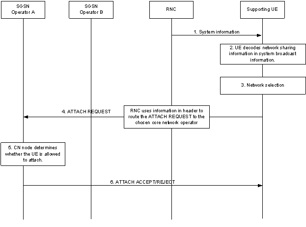
Step 1.
The UE reads the broadcast system information in the shared RAN.
Step 2.
A supporting UE decodes the shared network information and supplies the available core network operator PLMN-ids as candidates to the PLMN selection procedure. Only PLMNs in the Multiple PLMN ID List are candidates for network selection.
Step 3.
The UE performs network selection among available PLMNs.
Step 4.
The UE sends an ATTACH REQUEST message to the network. It also indicates to the RNC the chosen core network operator. The RNC uses the routing information to determine which core network operator the message should be routed to and the ATTACH REQUEST message is sent to the core network operator chosen by the UE.
Step 5.
The core network determines whether the UE is allowed to attach to the network.
Step 6.
The shared core network node sends the appropriate ACCEPT/REJECT message back to the UE. In case of an ATTACH ACCEPT message, the core network assigns the UE an appropriate TMSI/P-TMSI so that this identity can be used for any further rerouting of messages by the RNC.
7.1.5.2 GERAN based MOCN configuration |R10| p. 31
Supporting UEs can make use of the additional information in the broadcast system information. The GERAN signalling flow is shown in the figure below.
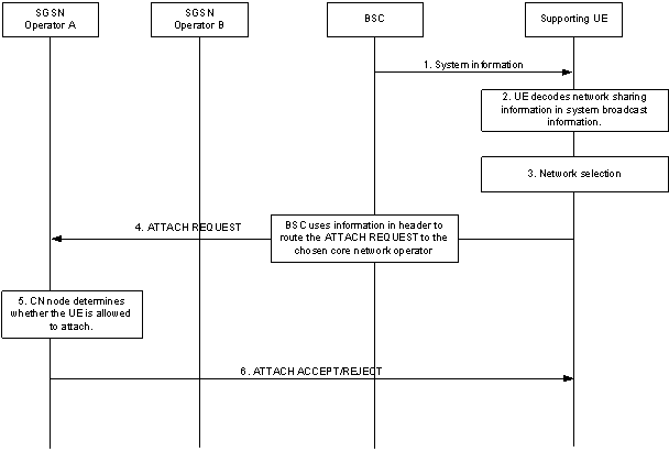
Step 1.
The UE reads the broadcast system information in the shared RAN.
Step 2.
A supporting UE decodes the shared network information and supplies the available core network operator PLMN-ids as candidates to the PLMN selection procedure. Only PLMNs in the Multiple PLMN ID List are candidates for network selection.
Step 3.
The UE performs network selection among available PLMNs.
Step 4.
The UE sends an ATTACH REQUEST message to the network. It also indicates to the BSC the chosen core network operator (via Initial L3 message for CS domain, via AS signalling for the PS domain). The BSC uses the routing information to determine which core network operator the message should be routed to and the ATTACH REQUEST message is sent to the core network operator chosen by the UE together with the chosen PLMN-id.
Step 5.
The core network determines whether the UE is allowed to attach to the network.
Step 6.
The core network node sends the appropriate ACCEPT/REJECT message back to the UE. In case of an ATTACH ACCEPT message, the core network assigns the UE an appropriate TMSI/P-TMSI so that this identity can be used for any further rerouting of messages by the BSC.
7.1.6 Query to opposite domain |R13| p. 32
The RAN may query the CN nodes in the opposite domain whether the UE is served by any of the sharing operators in the opposite domain. In the example below a registration attempt is made in the CS domain and the query in the opposite domain is sent to the PS domain i.e. the SGSNs and if not registered in the SGSN the SGSN sends the query to all MMEs that may hold the UEs context. If the registration attempt was made in the PS domain the query to opposite domain is send to the CS domain i.e. the MSCs.
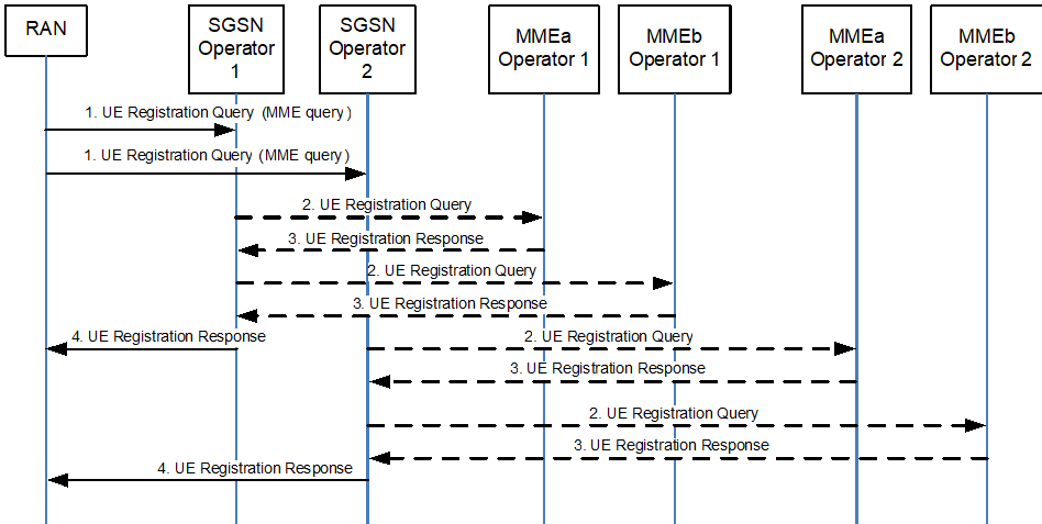
Step 1.
The SGSN receives a UE (IMSI) query from the RAN node including an indication to also query MMEs if the UE is not served by the SGSN.
Step 2.
If the UE is not served by the SGSN the SGSN forwards the UE (IMSI) query to all MMEs that may hold the UEs context of the same operator as the SGSN.
Step 3.
If the UE is not served by any node in E-UTRAN each MME replies with a negative response to the UE query. If the UE is served by any of the MMEs, this MME replies with a positive response.
Step 4.
If the SGSN or any MME serves the UE, the SGSN replies with a positive response to the UE query from RAN. If the UE is not served by any SGSN or MME, the SGSN replies with a negative response to RAN.
![]()
![]()
![]()