Content for TS 23.251 Word version: 17.0.0
7.1.4 Non-supporting UEs in a MOCN configuration
7.1.4.1 UTRAN based MOCN configuration
7.1.4.2 GERAN based MOCN configuration
7.1.4.3 CS registration after PS Handover
...
...
7.1.4 Non-supporting UEs in a MOCN configuration p. 22
7.1.4.1 UTRAN based MOCN configuration |R10| p. 22
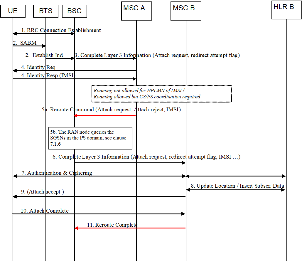
An example of an information flow for redirection in UTRAN is shown below.
In this example an attach request from a non-supporting UE is directed to three different CN operators. The UE is not a subscriber of any of the sharing operators. The UE is not served by any shared SGSN nor by any shared MSC. The UE is furthermore not under operator coordination. The first rejects since it has no roaming agreement with the subscribers Home PLMN or rejects due to CS/PS coordination required. The second rejects because of a roaming restriction found in HLR. The third CN operator accepts and completes the attach request. The different "MSC/SGSNs" in the example below shall be seen as different CN operators. One specific CN operator may also have several pooled MSCs/SGSNs connected to the RNC if Iu-flex is used.

Step 1.
If the RNC finds no more MSC/SGSN to redirect to after receiving a Reroute Command message, e.g. step 5 or step 9, it compares the cause code with cause codes from other Reroute Command messages it has earlier received for this UE. A cause code ranking is done and the "softest" cause code is chosen and the corresponding saved NAS attach reject message is returned to the UE.
Each CN node that receives an Initial UE, shall run its own authentication procedure. This may in some rare situations cause the UE to be authenticated more than once, however the trust-model used is that one CN operator shall not trust an authentication done by another CN operator. This will of course not be an optimal usage of radio resources, but given the rare occurrence of this, the increased signalling should not be of any significance.
During the redirect procedure the RNC keeps a timer, which corresponds to the UE timer of releasing the RR connection (20 seconds). If the RNC when receiving a Reroute Command message finds that there is not sufficient time for another redirect, further redirect attempts are stopped (for this attach request message). The UE will repeat its attach request four times (each time waiting 15 seconds before it re-establishes the RR connection for another try).
The RRC connection is established.
Step 2.
RNC receives an Initial Direct Transfer from an UE. The RNC is configured to work in a Shared RAN MOCN, and therefore it forwards the NAS message in an Initial UE message with an additional redirect attempt flag set. The flag indicates that the MSC/SGSN shall respond to the attach request with a Reroute Command or Reroute Complete IE in the Direct Transfer message. Selection of CN node is based on NRI (valid or invalid) if present in IDNNS or by random selection.
A redirect attempt flag could also simply be the fact that the Initial UE message does not include any UE selected PLMN-ID, which a supporting UE would include. Redirect is never done for supporting UEs.
Step 3.
The MSC/SGSN receives the Initial UE with the redirect attempt flag set. It then knows it shall answer with a Reroute Command or Reroute Complete IE in the Direct Transfer message.
Step 4.
The MSC/SGSN needs the IMSI of the UE. It is retrieved either from old MSC / old SGSN or from the UE as in this example. By comparing the IMSI with the roaming agreements of the CN operator, the MSC/SGSN discovers that roaming is not allowed or that roaming is allowed but CS/PS coordination required. Attach procedure is aborted.
Step 5a.
A message is sent back to the RNC with two NAS messages, the attach reject message and the original attach request message received from the UE (alternatively the original NAS message may be stored in the RNC). The IMSI and an indication that the UE is attaching is also included in the message, plus a reject cause code to the RNC. The Reroute Command IE is in the Direct Transfer message.
Step 5b.
The RAN node concludes that UE is attaching. For attach in PS domain the RAN node queries the MSCs in the CS domain whether the UE (IMSI) is served by any of the sharing operators in the CS domain. For attach in CS domain the RAN node queries the SGSNs in the PS domain whether the UE (IMSI) is served by any of the sharing operators in the PS domain. For PS domain the SGSNs may need to query all MMEs that may hold the UEs context, refer to clause 7.1.6.
In this example the UE is yet neither served by a node in the CS domain nor in the PS domain. The signalling connection between RNC and MSC/SGSN A is released. Based on deterministic IMSI analysis the RNC selects a MSC/SGSN in the next step. If reject was due to CS/PS coordination required then the same operator may be selected again. If reject was not due to CS/PS coordination required then the already tried MSC/SGSNs is stored in the RNC during the redirect procedure so that the same node is not selected twice.
Step 6.
The RNC sends a new Initial UE to the next selected MSC/SGSN with the original NAS attach request message (in case of CS/PS coordination the Initial UE may also be sent back to the first MSC/SGSN depending on the outcome of the coordination). Redirect attempt flag is set and IMSI shall also be included to avoid a second IMSI retrieval from UE or old MSC/SGSN and to indicate that PS/CS domain coordination has been done in RNC. The CN operator selected by the RAN is included in the signalling from RAN to Core Network The MSC/SGSN receiving the message starts its attach procedure.
Step 7.
MSC/SGSN B does in general support roaming for the HPLMN of the IMSI and hence authentication is done and RAN ciphering is established.
Step 8.
MSC/SGSN B updates the HLR and receives subscriber data from HLR.
Step 9.
The subscription data do not allow roaming (e.g. regional or 3G). MSC/SGSN B sends a Reroute Command message including the attach reject message, a reject cause code, the original attach request message and the N(SD) (for MSC only). IMSI is included in Reroute Command message only if it was not included in the Initial UE received by the MSC/SGSN.
The signalling connection between the RNC and the MSC/SGSN B is released. The RNC then selects a new operator and a new MSC/SGSN based on deterministic IMSI analysis as in step 5b.
Step 10.
The MSC/SGSN C receives an Initial UE (with the original NAS attach request message) with the redirect attempt flag is set, an IMSI, and N(SD) (if MSC). The MSC/SGSN C also receives the CN operator selected by the RAN. The MSC/SGSN C starts the attach procedure and uses provided information (IMSI and N(SD)).
Step 11.
MSC/SGSN C does in general support roaming for the HPLMN of the IMSI and hence authentication is done and RAN ciphering is established.
Step 12.
MSC/SGSN C updates the HLR and receives subscriber data from HLR. Subscriber data allows roaming, and the MSC/SGSN C completes the attach procedure. This includes the assignment of a new TMSI/P-TMSI with an NRI that can be used by RNC to route subsequent signalling between UE and correct MSC/SGSN (Iu-flex functionality). The Update Location sent to HLR also triggers a Cancel Location sent to the MSC/SGSN B.
Step 13.
A Reroute Complete IE in the Direct Transfer message with the NAS Attach accept message is sent to RNC. By this, the RNC knows that the redirect is finished and can both forward the NAS message to the UE and clean up any stored redirect data.
Step 14.
The Attach Accept is forwarded to the UE. The UE stores the TMSI/P-TMSI with the Iu-flex NRI to be used for future signalling, even after power off.
Step 15.
UE responds with an Attach Complete message.
7.1.4.2 GERAN based MOCN configuration |R10| p. 25
An example of an information flow for redirection in GERAN is shown below.
In this example an attach request from a non-supporting UE is directed to two different CN operators. The UE is not a subscriber of any of the sharing operators. The UE is not served by any shared SGSN nor by any shared MSC. The UE is furthermore not under operator coordination. The first CN operator rejects since it has no roaming agreement with the subscribers Home PLMN or rejects due to CS/PS coordination required. The second CN operator accepts and completes the attach request. The different "MSC/SGSNs" in the example below shall be seen as different CN operators. One specific CN operator may also have several pooled MSCs/SGSNs connected to the BSC if A/Gb-Flex is used.
Separate call flows are shown for CS domain and for PS domain.
Step 1.
If the BSC finds no more MSC to redirect to after receiving a Reroute Command message, it compares the cause code with cause codes from other Reroute Command messages it has earlier received for this UE. A cause code ranking is done and the "softest" cause code is chosen and the corresponding saved attach reject message is returned to the UE.
Each CN node that receives a Complete Layer 3 Information shall run its own authentication procedure. This may in some rare situations cause the UE to be authenticated more than once, however the trust-model used is that one CN operator shall not trust an authentication done by another CN operator. This will of course not be an optimal usage of radio resources, but given the rare occurrence of this, the increased signalling should not be of any significance.
During the redirect procedure the BSC keeps a timer, which corresponds to the UE timer of releasing the RR connection (20 seconds). If the BSC when receiving a Reroute Command message finds that there is not sufficient time for another redirect, further redirect attempts are stopped (for this attach request message). The UE will repeat its attach request four times (each time waiting 15 seconds before it re-establishes the RR connection for another try).
The RRC connection is established.
Step 2.
BSC receives the Layer 3 message from an UE. The BSC is configured to work in a Shared RAN MOCN, and therefore it forwards the message in a Complete Layer 3 Information message with an additional redirect attempt flag set. The flag indicates that the MSC shall respond to the attach request with a Reroute Command message to inform the BSC that a redirection to another CN has to be performed.
The selection of CN node is based on NRI (valid or invalid) or by random selection. The same mechanism as defined for A-Flex in TS 23.236 is used.
Step 3.
The MSC receives the Complete Layer 3 Information message with the redirect attempt flag set. It then knows it may have to provide the BSC with a Reroute Command message.
Step 4.
The MSC needs the IMSI of the UE. It is retrieved either from old MSC or from the UE as in this example. By comparing the IMSI with the roaming agreements of the CN operator, the MSC A discovers that roaming is not allowed or that roaming is allowed but CS/PS coordination required. Attach procedure is aborted.
Step 5a.
A Reroute Command message is sent back to the BSC with the attach reject message and the original attach request message received from the UE. The IMSI and an indication that the UE is attaching is also included in the message, plus a reject cause code to the BSC.
Step 5b.
The BSC concludes that UE is attaching. The BSC node queries the SGSNs in the PS domain whether the UE (IMSI) is served by any of the sharing operators in the PS domain. The SGSNs may need to query all MMEs that may hold the UEs context, refer to clause 7.1.6.
In this example the UE is yet not served by a node in the PS domain. The signalling connection between BSC and MSC A is released. Based on deterministic IMSI analysis the BSC selects a MSC B in the next step. If reject was not due to CS/PS coordination required then the already tried MSC A is stored in the BSC during the redirect procedure so that the same node is not selected twice.
Step 6.
The BSC sends a new Complete Layer 3 Information to the next selected MSC B with the original attach request message (in case of CS/PS coordination the Complete Layer 3 Information may also be sent back to the first MSC depending on the outcome of the coordination). Redirect attempt flag is set and IMSI shall also be included to avoid a second IMSI retrieval from UE or old MSC and to indicate that PS/CS domain coordination has been done in BSC. The CN operator selected by the BSC is included in the signalling from BSC to Core Network. The MSC B receiving the message starts its attach procedure.
Step 7.
MSC B does in general support roaming for the HPLMN of the IMSI and hence authentication is done and RAN ciphering is established.
Step 8.
MSC B updates the HLR and receives subscriber data from HLR. Subscriber data allows roaming, and the MSC B completes the attach procedure. This includes the assignment of a new TMSI with an NRI that can be used by BSC to route subsequent signalling between UE and correct MSC (A-Flex functionality).
Step 9.
The Attach Accept is forwarded to the UE. The UE stores the TMSI with the A-Flex NRI to be used for future signalling, even after power off. This is existing functionality.
Step 10.
UE responds with an Attach Complete message (TMSI (re-)allocation if not already made in Attach accept).
Step 11.
A Reroute Complete message is sent to BSC. The BSC knows that the redirect is completed and clean up any stored redirect data.
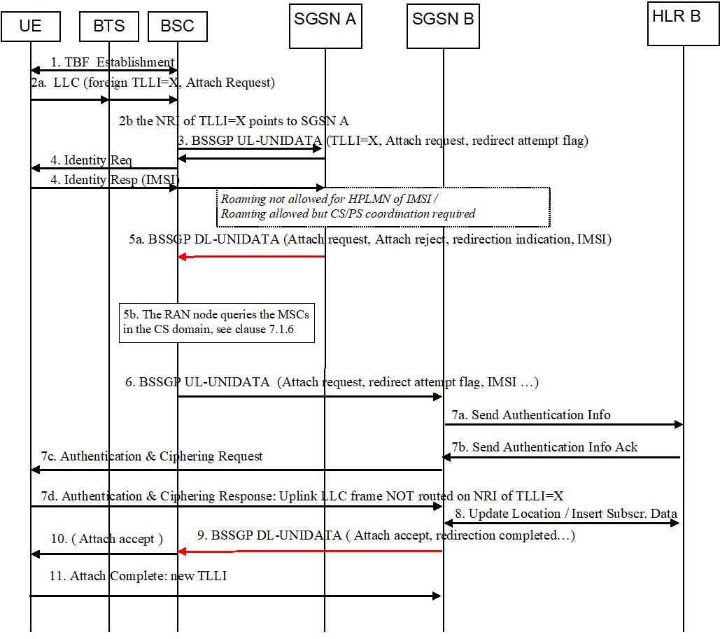
Step 1.
If the BSC finds no more SGSN to redirect to after receiving a BSSGP DL-UNITDATA message with the redirection indication flag set, it compares the cause code with cause codes from other BSSGP DL-UNITDATA messages it has earlier received for this UE. A cause code ranking is done and the "softest" cause code is chosen and the corresponding saved attach reject message is returned to the UE.
Each CN node that receives a BSSGP UL-UNITDATA, shall run its own authentication procedure. This may in some rare situations cause the UE to be authenticated more than once, however the trust-model used is that one CN operator shall not trust an authentication done by another CN operator. This will of course not be an optimal usage of radio resources, but given the rare occurrence of this, the increased signalling should not be of any significance.
During the redirect procedure the BSC keeps a timer, which corresponds to the UE timer of releasing the RR connection (20 seconds). If the BSC when receiving a BSSGP DL-UNITDATA message with the redirection indication flag set finds that there is not sufficient time for another redirect, further redirect attempts are stopped (for this attach request message). The UE will repeat its attach request four times (each time waiting 15 seconds before it re-establishes the RR connection for another try).
The TBF is established.
Step 2, 2a.
BSC receives the LLC frame with foreign [or random] TLLI =X.
The BSC is configured to work in a Shared RAN MOCN, and therefore it forwards the message in a BSSGP UL-UNITDATA message with an additional redirect attempt flag set. The flag indicates that the SGSN shall respond to the attach request with a BSSGP DL-UNITDATA message providing when relevant a redirection indication flag set to inform the BSC that a redirection to another CN has to be performed.
The selection of CN node is based on NRI (valid or invalid) or by random selection. The same mechanism as defined for Gb-Flex in TS 23.236 is used.
Step 3.
The SGSN receives the BSSGP UL-UNITDATA message with the redirect attempt flag set. It then knows it may have to provide the BSC with a redirection indication flag set or a redirection completed flag set.
Step 4.
The SGSN needs the IMSI of the UE. It is retrieved either from old SGSN or from the UE as in this example. By comparing the IMSI with the roaming agreements of the CN operator, the SGSN A discovers that roaming is not allowed or that roaming is allowed but CS/PS coordination required. Attach procedure is aborted.
Step 5a.
A BSSGP DL-UNITDATA message is sent back to the BSC with a redirection indication flag set containing the reject cause, the attach reject message and the original attach request message received from the UE. The V(U) used for LLC-PDU setting (refer to TS 44.064) is included in the message. The IMSI and an indication that the UE is attaching is also included in the message.
Step 5b.
The BSC node concludes that UE is attaching. The BSC node queries the MSCs in the CS domain whether the UE (IMSI) is served by any of the sharing operators in the CS domain.
In this example the UE is yet not served by any node in the CS domain. Based on deterministic IMSI analysis the BSC selects a SGSN B in the next step. If reject was not due to CS/PS coordination required then the already tried SGSN A is stored in the BSC during the redirect procedure so that the same node is not selected twice.
The BSC makes a short-lived binding between the TLLI =X and SGSN ID so that it points to SGSN B.
Step 6.
The BSC sends a new BSSGP UL-UNITDATA to the next selected SGSN B with the original attach request message (in case of CS/PS coordination the BSSGP UL-UNITDATA may also be sent back to the first SGSN depending on the outcome of the coordination). Redirect attempt flag is set and IMSI shall be included to avoid a second IMSI retrieval from UE or old SGSN and to indicate that PS/CS domain coordination has been done in BSC. The V(U) shall also be included in the message. The CN operator selected by the BSC is included in the signalling from BSC to Core Network. The SGSN B receiving the message starts its attach procedure.
Step 7.
SGSN B does in general support roaming for the HPLMN of the IMSI and hence authentication is done and RAN ciphering is established. The value of V(U) in SGSN-B shall be set according to the received value from BSC.
Uplink LLC frames shall be routed to SGSN B despite the NRI of the TLLI=X pointing to SGSN A.
Step 8.
SGSN B updates the HLR and receives subscriber data from HLR. Subscriber data allows roaming, and the SGSN B completes the attach procedure. This includes the assignment of a new P-TMSI with an NRI that can be used by BSC to route subsequent signalling between UE and correct SGSN (Gb-Flex functionality).
Step 9.
A BSSGP DL-UNITDATA Attach accept message is sent to BSC with the redirection completed flag set . The BSC knows that the redirect is finished and can both forward the Attach Accept message to the UE and clean up any stored redirect data.
SGSN B is allowed to reset the XID parameter only after the attach request is accepted.
Step 10.
The Attach Accept is forwarded to the UE. The UE stores the P-TMSI with the Gb-Flex NRI to be used for future signalling, even after power off. This is existing functionality.
Step 11.
UE responds with an Attach Complete message (P-TMSI (re-)allocation if not already made in Attach Accept). The Attach Complete uses new TLLI. After this, the BSS releases the binding between TLLI=X and SGSN B.
7.1.4.3 CS registration after PS Handover |R13| p. 28
An example of an information flow at registration in current domain when already registered in opposite domain is shown below.
This example shows network selection for a non-supporting UE in a shared UTRAN network. The UE is not a subscriber of any of the sharing operators. The UE is not under operator coordination. Due to PS Handover the UE is registered in the PS domain of the shared UTRAN network when the registration attempt for the CS domain occurs.
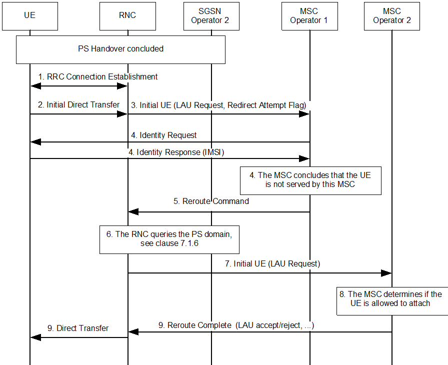
Figure 7-2: Information flow for registration in CS domain after PS Handover
(⇒ copy of original 3GPP image)
(⇒ copy of original 3GPP image)
Step 1.
The RRC connection is established.
Step 2.
RNC receives an Initial Direct Transfer from an UE. The RNC is configured to work in a Shared RAN MOCN, and therefore it forwards the NAS message in an Initial UE message with an additional redirect attempt flag set. The flag indicates that the MSC shall respond to the attach request with a Reroute Command or Reroute Complete IE in the Direct Transfer message. Selection of CN node is based on NRI (valid or invalid) if present in IDNNS or by random selection. The RAN stores the NRI received from the UE.
Step 3.
The MSC receives the Initial UE with the redirect attempt flag set. It then knows it shall answer with a Reroute Command or Reroute Complete IE in the Direct Transfer message.
Step 4.
The MSC needs the IMSI of the UE. It is retrieved either from old MSC or from the UE as in this example. By comparing the IMSI with the roaming agreements of the CN operator, the MSC discovers that the UE has no subscription in operator's network. The MSC concludes also that the UE is not served by the MSC.
Step 5.
A Reroute Command message is sent back to the RNC with an indication that it is for CSPS coordination purposes. The Reroute Command message includes the IMSI, the LAU REJECT message and the original LOCATION AREA UPDATE message received from the UE. Included is also old LAI. The Reroute Command IE is in the Direct Transfer message.
Step 6.
The RNC concludes that the UE is not under operator coordination. The RNC queries the SGSNs in the PS domain whether the UE (IMSI) is served by any of the sharing operators in the PS domain. The SGSNs may need to query all MMEs that may hold the UEs context, refer to clause 7.1.6.
Step 7.
In this example the UE is served by an SGSN node in the PS domain. The RNC selects the same operator for the CS domain and sends the Initial UE to an MSC belonging to the selected operator. The operator selected by the RNC is included in the signalling from RNC to MSC. The redirect attempt flag and an indication that the UE in the PS domain is served by the RNC selected operator shall also be included.
Step 8.
The MSC determines whether the UE is allowed to attach.
Step 9.
The MSC sends the appropriate ACCEPT/REJECT message back to the UE.
![]()
![]()
![]()