Content for TS 23.107 Word version: 18.0.0
6 QoS Architecture
6.1 Overview of Different Levels of QoS
6.2 QoS Management Functions in the Network
6.3 UMTS QoS Classes
...
...
6 QoS Architecture p. 9
6.1 Overview of Different Levels of QoS p. 9
Network Services are considered end-to-end, this means from a Terminal Equipment (TE) to another TE. An End-to-End Service may have a certain Quality of Service (QoS) which is provided for the user of a network service. It is the user that decides whether he is satisfied with the provided QoS or not.
To realise a certain network QoS a Bearer Service with clearly defined characteristics and functionality is to be set up from the source to the destination of a service.
A bearer service includes all aspects to enable the provision of a contracted QoS. These aspects are among others the control signalling, user plane transport and QoS management functionality. A UMTS bearer service layered architecture is depicted in Figure 1, each bearer service on a specific layer offers it's individual services using services provided by the layers below.
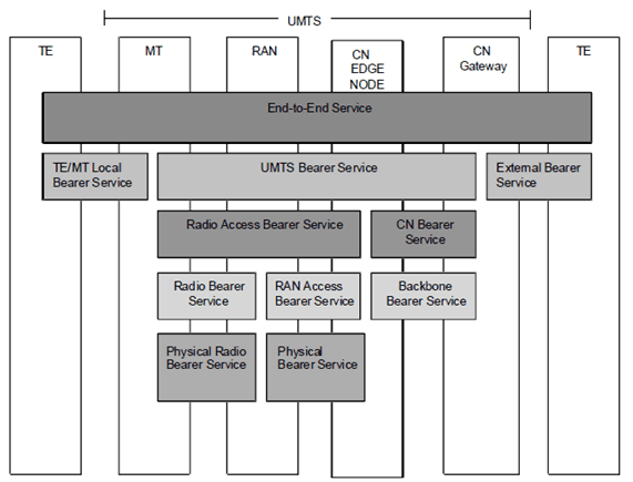
6.1.1 The End-to-End Service and UMTS Bearer Service p. 10
On its way from the TE to another TE the traffic has to pass different bearer services of the network(s). A TE is connected to the UMTS network by use of a Mobile Termination (MT). The End-to-End Service on the application level uses the bearer services of the underlying network(s). As the End-to-End Service is conveyed over several networks (not only UMTS) it is not subject for further elaboration in the present document.
The End-to-End-Service used by the TE will be realised using a TE/MT Local Bearer Service, a UMTS Bearer Service, and an External Bearer Service.
TE/MT Local Bearer Service is not further elaborated here as this bearer service is outside the scope of the UMTS network.
Having said that the End-to-End Bearer Service is beyond the scope of the present document it is however the various services offered by the UMTS Bearer Service that the UMTS operator offers. It is this bearer service that provides the UMTS QoS.
The External Bearer Service is not further elaborated here as this bearer may be using several network services, e.g. another UMTS Bearer Service.
6.1.2 The Radio Access Bearer Service and the Core Network Bearer Service p. 10
As described in the previous clause it is the UMTS Bearer Service that provides the UMTS QoS. The UMTS Bearer Service consists of two parts, the Radio Access Bearer Service and the Core Network Bearer Service. Both services reflects the optimised way to realise the UMTS Bearer Service over the respective cellular network topology taking into account such aspects as e.g. mobility and mobile subscriber profiles.
The Radio Access Bearer Service provides confidential transport of signalling and user data between MT and CN Edge Node with the QoS adequate to the negotiated UMTS Bearer Service or with the default QoS for signalling. This service is based on the characteristics of the radio interface and is maintained for a moving MT.
If unequal error protection shall be supported, it is provided by underlying Radio Bearer Services. In this case the payload of the user data SDU, transported by the Radio Access Bearer Service, shall conform to a SDU format defined with possible exact sizes and the payload bits statically structured per size. Each bit of the SDU payload belongs to a defined subflow. At Radio Access Bearer Service establishment, the exact SDU payload format and required reliability per subflow is signalled to RAN using standardised attributes (see clause 6.4.3).
In release 1999, unequal error protection for a Radio Access Bearer is only applicable for services using a codec integrated in the core network. This implies that UMTS Bearer service can not use the attribute SDU format information to define subflows and the payload bits of the SDUs will therefore be equally protected.
The Core Network Bearer Service of the UMTS core network connects the UMTS CN Edge Node with the CN Gateway to the external network. The role of this service is to efficiently control and utilise the backbone network in order to provide the contracted UMTS bearer service. The UMTS packet core network shall support different backbone bearer services for variety of QoS.
6.1.3 The Radio Bearer Service and the RAN Access Bearer Service p. 11
The Radio Access Bearer Service is realised by a Radio Bearer Service and an RAN Access -Bearer Service.
The Radio Bearer Service covers all the aspects of the radio interface transport. This bearer service is provided by the UTRAN FDD/TDD or the GERAN, which are not elaborated further in the present document.
To support unequal error protection, RAN and MT shall have the ability to segment/reassemble the user flows into the different subflows requested by the Radio Access Bearer Service. The segmentation/ reassemble is given by the SDU payload format signalled at Radio Access Bearer establishment. The Radio Bearer service handles the part of the user flow belonging to one subflow, according to the reliability requirements for that subflow.
The RAN Access Bearer Service together with the Physical Bearer Service provides the transport between RAN and CN. RAN Access bearer services for packet traffic shall provide different bearer services for variety of QoS. The RAN Access Bearer Service is provided by the Iu or the Gb Bearer Service.
6.1.4 The Backbone Network Service p. 11
The Core Network Bearer Service uses a generic Backbone Network Service.
The Backbone Network Service covers the layer 1/Layer2 functionality and is selected according to operator's choice in order to fulfil the QoS requirements of the Core Network Bearer Service. The Backbone Network Service is not specific to UMTS but may reuse an existing standard.
6.2 QoS Management Functions in the Network p. 11
The purpose of this clause is to give a comprehensive overview of functionality needed to establish, modify and maintain a UMTS Bearer Service with a specific QoS. The relations between the functions internal to the nodes are implementation specific. The allocation of these functions to the UMTS entities shall indicate the requirement for the specific entity to enforce the QoS commitments negotiated for the UMTS bearer service. The specific realisation of these functions is implementation dependent and has only to maintain the specified QoS characteristics. The QoS management functions of all UMTS entities together shall ensure the provision of the negotiated service between the access points of the UMTS bearer service. The end-to-end service is provided by translation/mapping with UMTS external services.
6.2.1 Description of functions p. 12
6.2.1.1 QoS management functions for UMTS bearer service in the control plane p. 12
Service Manager co-ordinates the functions of the control plane for establishing, modifying and maintaining the service it is responsible for. And, it provides all user plane QoS management functions with the relevant attributes. The service manager offers services to other instances, it signals with peer service managers and uses services provided by other instances. The service manager may perform an attribute translation to request lower layer services. Furthermore, it may interrogate other control functions to receive permission for service provision.
Translation function converts between the internal service primitives for UMTS bearer service control and the various protocols for service control of interfacing external networks. The translation includes the converting between UMTS bearer service attributes and QoS attributes of the external networks service control protocol (e.g. between IETF TSPEC and UMTS service attributes). The service manager may include a translation function to convert between its service attributes and the attributes of a lower layer service it is using.
Admission/Capability Control maintains information about all available resources of a network entity and about all resources allocated to UMTS bearer services. It determines for each UMTS bearer service request or modification whether the required resources can be provided by this entity and it reserves these resources if allocated to the UMTS bearer service. The function checks also the capability of the network entity to provide the requested service, i.e. whether the specific service is implemented and not blocked for administrative reasons. The resource control performed by the admission control supports also the service retention.
Subscription Control checks the administrative rights of the UMTS bearer service user to use the requested service with the specified QoS attributes.
6.2.1.2 Functions for UMTS bearer service in the user plane p. 12
User plane QoS management functions maintain the signalling and user data traffic within certain limits, defined by specific QoS attributes. UMTS bearer services with different QoS attribute values shall be supported by the QoS management functions. These functions ensure the provision of the QoS negotiated for a UMTS bearer service.
Mapping function provides each data unit with the specific marking required to receive the intended QoS at the transfer by a bearer service.
Classification function assigns data units to the established services of a MT according to the related QoS attributes if the MT has multiple UMTS bearer services established. The appropriate UMTS bearer service is derived from the data unit header or from traffic characteristics of the data.
Resource Manager distributes the available resources between all services sharing the same resource. The resource manager distributes the resources according to the required QoS. Example means for resource management are scheduling, bandwidth management and power control for the radio bearer.
Traffic conditioner provides conformance between the negotiated QoS for a service and the data unit traffic. Traffic conditioning is performed by policing or by traffic shaping. The policing function compares the data unit traffic with the related QoS attributes. Data units not matching the relevant attributes will be dropped or marked as not matching, for preferential dropping in case of congestion. The traffic shaper forms the data unit traffic according to the QoS of the service. The reference algorithm for traffic conditioning is described in Annex B. This reference algorithm should not be interpreted as a required implementation algorithm.
6.2.2 Allocation of QoS management functions p. 12
6.2.2.1 QoS management functions for UMTS bearer service in the control plane p. 12
The QoS management functions for controlling the UMTS bearer service are shown in Figure 2. These control functions support the establishment and the modification of a UMTS bearer service by signalling/negotiation with the UMTS external services and by the establishment or modification of all UMTS internal services with the required characteristics.
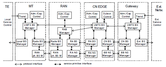
Figure 2: QoS management functions for UMTS bearer service in the control plane
(⇒ copy of original 3GPP image)
(⇒ copy of original 3GPP image)
The translation functions (Trans.) in the MT and the Gateway convert between external service signalling and internal service primitives including the translation of the service attributes. The translation function in the Gateway is FFS regarding packet oriented services.
The UMTS BS manager in the MT, CN EDGE and the Gateway signal between each other and via the translation function with external instances to establish or modify a UMTS bearer service. Each of the UMTS BS managers interrogates its associated admission/capability control whether the network entity supports the specific requested service and whether the required resources are available. Additionally, the CN EDGE UMTS BS manager verifies with the subscription control the administrative rights for using the service.
The UMTS BS manager of the MT translates the UMTS bearer service attributes into attributes for the local bearer service and requests this service from the local BS manager.
The UMTS BS manager of the CN EDGE translates the UMTS bearer service attributes into RAB service attributes and RAN Access bearer service attributes and it translates UMTS bearer service attributes into CN bearer service attributes. Also, the UMTS BS manager of the CN EDGE requests its RAN Access BS manager, its CN BS manager and the RAB manager in the RAN to provide the required services.
The RAB manager verifies with its admission/capability control whether the RAN supports the specific requested service and whether the required resources are available. It translates the RAB service attributes into radio bearer service and RAN Access bearer service attributes and requests the radio BS manager and the RAN Access BS manager to provide bearer services with the required attributes.
The Gateway UMTS BS manager translates the UMTS bearer service attributes into CN bearer service attributes and requests its CN BS manager to provide the service. Furthermore, it translates the UMTS bearer service attributes into the external bearer service attributes and requests this service from the external BS manager.
Radio, RAN Access and CN BS managers use services provided by lower layers as indicated in Figure 2.
6.2.2.2 QoS management functions for the UMTS bearer service in the user plane p. 14
The QoS management functions of the UMTS BS for the user plane are shown in Figure 3. These functions maintain the data transfer characteristics according to the commitments established by the UMTS BS control functions and expressed by the bearer service attributes. The QoS management user plane functions are provided with the relevant attributes by the QoS management control functions.
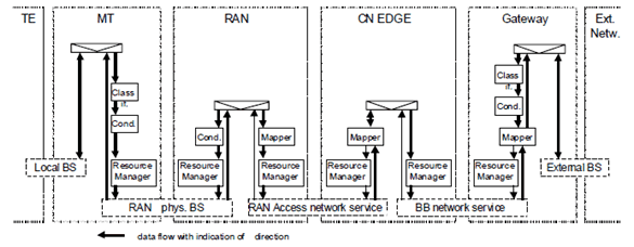
Figure 3: QoS management functions for the UMTS bearer service in the user plane
(⇒ copy of original 3GPP image)
(⇒ copy of original 3GPP image)
The classification function (Class.) in the Gateway and in the MT assign user data units received from the external bearer service or the local bearer service to the appropriate UMTS bearer service according to the QoS requirements of each user data unit. The classification function in the MT is FFS.
The traffic conditioner (Cond.) in the MT provides conformance of the uplink user data traffic with the QoS attributes of the relevant UMTS bearer service. In the Gateway a traffic conditioner may provide conformance of the downlink user data traffic with the QoS attributes of the relevant UMTS bearer service; i.e. on a per PDP context basis. In addition, the traffic conditioner in the Gateway may provide conformance of the uplink and downlink user data traffic with QoS attributes related to the whole non-guaranteed bit-rate traffic of a UE for an APN (i.e. APN-AMBR). The packet oriented transport of the downlink data units from the external bearer service to the RAN and the buffering in the RAN may result in bursts of downlink data units not conformant with the UMTS BS QoS attributes. A traffic conditioner in the RAN forms this downlink data unit traffic according to the relevant QoS attributes. In addition, the traffic conditioner in the RAN may provide conformance of the uplink and downlink user data traffic (traffic) with QoS attributes related to the whole non-guaranteed bit-rate traffic of a UE (i.e. UE-AMBR).
The traffic conditioners are not necessarily separated functions. For example a resource manager may also provide conformance with the relevant QoS attributes by appropriate data unit scheduling. Or, if fixed resources are dedicated to one bearer service the resource limitations implicitly condition the traffic.
The mapping function marks each data unit with the specific QoS indication related to the bearer service performing the transfer of the data unit.
Each of the resource managers of a network entity is responsible for a specific resource. The resource manager distributes its resources between all bearer services requesting transfer of data units on these resources. Thereby, the resource manager attempts to provide the QoS attributes required for each individual bearer service.
6.3 UMTS QoS Classes p. 15
When defining the UMTS QoS classes, also referred to as traffic classes, the restrictions and limitations of the air interface have to be taken into account. It is not reasonable to define complex mechanisms as have been in fixed networks due to different error characteristics of the air interface. The QoS mechanisms provided in the cellular network have to be robust and capable of providing reasonable QoS resolution. Table 1 illustrates the QoS classes for UMTS.
There are four different QoS classes:
- conversational class;
- streaming class;
- interactive class; and
- background class.
6.3.1 Conversational class p. 15
The most well known use of this scheme is telephony speech (e.g. GSM). But with Internet and multimedia a number of new applications will require this scheme, for example voice over IP and video conferencing tools. Real time conversation is always performed between peers (or groups) of live (human) end-users. This is the only scheme where the required characteristics are strictly given by human perception.
Real time conversation scheme is characterised by that the transfer time shall be low because of the conversational nature of the scheme and at the same time that the time relation (variation) between information entities of the stream shall be preserved in the same way as for real time streams. The maximum transfer delay is given by the human perception of video and audio conversation. Therefore the limit for acceptable transfer delay is very strict, as failure to provide low enough transfer delay will result in unacceptable lack of quality. The transfer delay requirement is therefore both significantly lower and more stringent than the round trip delay of the interactive traffic case.
Real time conversation - fundamental characteristics for QoS:
- preserve time relation (variation) between information entities of the stream;
- conversational pattern (stringent and low delay).
6.3.2 Streaming class p. 16
When the user is looking at (listening to) real time video (audio) the scheme of real time streams applies. The real time data flow is always aiming at a live (human) destination. It is a one way transport.
This scheme is one of the newcomers in data communication, raising a number of new requirements in both telecommunication and data communication systems. It is characterised by that the time relations (variation) between information entities (i.e. samples, packets) within a flow shall be preserved, although it does not have any requirements on low transfer delay.
The delay variation of the end-to-end flow shall be limited, to preserve the time relation (variation) between information entities of the stream. But as the stream normally is time aligned at the receiving end (in the user equipment), the highest acceptable delay variation over the transmission media is given by the capability of the time alignment function of the application. Acceptable delay variation is thus much greater than the delay variation given by the limits of human perception.
Real time streams - fundamental characteristics for QoS:
- preserve time relation (variation) between information entities of the stream.
6.3.3 Interactive class p. 16
When the end-user, that is either a machine or a human, is on line requesting data from remote equipment (e.g. a server), this scheme applies. Examples of human interaction with the remote equipment are: web browsing, data base retrieval, server access. Examples of machines interaction with remote equipment are: polling for measurement records and automatic data base enquiries (tele-machines).
Interactive traffic is the other classical data communication scheme that on an overall level is characterised by the request response pattern of the end-user. At the message destination there is an entity expecting the message (response) within a certain time. Round trip delay time is therefore one of the key attributes. Another characteristic is that the content of the packets shall be transparently transferred (with low bit error rate).
Interactive traffic - fundamental characteristics for QoS:
- request response pattern;
- preserve payload content.
6.3.4 Background class p. 16
When the end-user, that typically is a computer, sends and receives data-files in the background, this scheme applies. Examples are background delivery of E-mails, SMS, download of databases and reception of measurement records.
Background traffic is one of the classical data communication schemes that on an overall level is characterised by that the destination is not expecting the data within a certain time. The scheme is thus more or less delivery time insensitive. Another characteristic is that the content of the packets shall be transparently transferred (with low bit error rate).
Background traffic - fundamental characteristics for QoS:
- the destination is not expecting the data within a certain time;
- preserve payload content.
| Traffic class | Conversational class conversational RT |
Streaming class streaming RT |
Interactive class Interactive best effort |
Background Background best effort |
|---|---|---|---|---|
| Fundamental characteristics | Preserve time relation (variation) between information entities of the stream Conversational pattern (stringent and low delay) | Preserve time relation (variation) between information entities of the stream | Request response pattern Preserve payload content | Destination is not expecting the data within a certain time Preserve payload content |
| Example of the application | voice | streaming video | Web browsing | background download of emails |
![]()
![]()
![]()