Content for TS 23.040 Word version: 18.0.0
0…
3…
3.3…
4…
8…
9…
9.2…
9.2.2.2…
9.2.2.3…
9.2.3…
9.2.3.12…
9.2.3.24
9.2.3.24.1…
9.2.3.24.10…
9.2.3.24.10.1.12…
9.2.3.24.10.2…
9.2.3.24.11…
9.2.3.25…
9.3…
10…
10.1.1…
10.1.3…
10.1.5…
10.1.7…
10.1.9…
10.1.11…
10.1.13…
10.1.15…
10.1.17…
10.2
10.2.1…
10.2.3…
10.2.5…
10.2.7…
10.3
11…
A…
C
C.1…
C.3…
C.5…
C.7…
C.9…
C.11…
C.13…
C.15…
D…
E…
F…
G…
G.2…
G.6
G.7
H…
I…
J…
K…
9.2.3.24 TP-User Data (TP-UD) p. 71
The length of the TP-User-Data field is defined in the PDU's of the SM-TL (see clause 9.2.2).
The TP-User-Data field may comprise just the short message itself or a Header in addition to the short message depending upon the setting of TP-UDHI.
Where the TP-UDHI value is set to 0 the TP-User-Data field comprises the short message only, where the user data can be 7 bit (default alphabet) data, 8 bit data, or 16 bit (UCS2 [24]) data.
Where the TP-UDHI value is set to 1 the first octets of the TP-User-Data field contains a Header in the following order starting at the first octet of the TP-User-Data field.
Irrespective of whether any part of the User Data Header is ignored or discarded, the MS shall always store the entire TPDU exactly as received.
| FIELD | LENGTH |
|---|---|
| Length of User Data Header | 1 octet |
| Information-Element-Identifier "A" | 1 octet |
| Length of Information-Element "A" | 1 octet |
| Information-Element "A" Data | 0 to "n" octets |
| Information-Element-Identifier "B" | 1 octet |
| Length of Information-Element "B" | 1 octet |
| Information-Element "B" Data | 0 to "n" octets |
| Information-Element-Identifier "X" | 1 octet |
| Length of Information-Element "X" | 1 octet |
| Information-Element "X" Data | 0 to "n" octets |
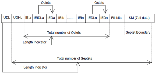
The diagram below shows the layout of the TP-User-Data-Length and the TP-User-Data for uncompressed GSM 7 bit default alphabet data. The UDHL field is the first octet of the TP-User-Data content of the Short Message.

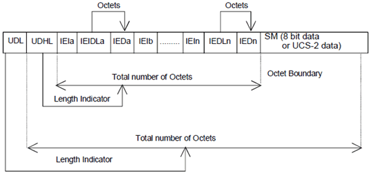
The diagram below shows the layout of the TP-User-Data-Length and the TP-User-Data for uncompressed 8 bit data or uncompressed UCS2 data. The UDHL field is the first octet of the TP-User-Data content of the Short Message.

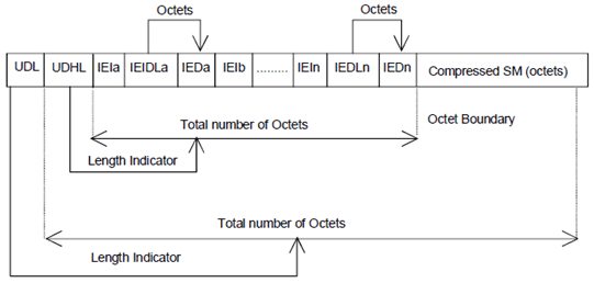
The diagram below shows the layout of the TP-User-Data-Length and the TP-User-Data for compressed GSM 7 bit default alphabet data, compressed 8 bit data or compressed UCS2 data. The UDHL field is the first octet of the TP-User-Data content of the Short Message.

The definition of the TP-User-Data-Length field which immediately precedes the "Length of User Data Header" is unchanged and shall therefore be the total length of the TP-User-Data field including the Header, if present. (see clause 9.2.3.16).
The "Length-of-Information-Element" fields shall be the integer representation of the number of octets within its associated "Information-Element-Data" field which follows and shall not include itself in its count value.
The "Length-of-User-Data-Header" field shall be the integer representation of the number of octets within the "User-Data-Header" information fields which follow and shall not include itself in its count or any fill bits which may be present (see text below).
Information Elements may appear in any order and need not follow the order used in the present document. Information Elements are classified into 3 categories as described below.
- SMS Control - identifies those IEIs which have the capability of dictating SMS functionality.
- EMS Control - identifies those IEIs which manage EMS Content IEIs.
- EMS Content - identifies those IEIs containing data of a unique media format.
| VALUE (hex) | MEANING | Classification | Repeatability |
|---|---|---|---|
| 00 | Concatenated short messages, 8-bit reference number | SMS Control | No |
| 01 | Special SMS Message Indication | SMS Control | Yes |
| 02 | Reserved | N/A | N/A |
| 03 | Value not used to avoid misinterpretation as <LF> character | N/A | N/A |
| 04 | Application port addressing scheme, 8 bit address | SMS Control | No |
| 05 | Application port addressing scheme, 16 bit address | SMS Control | No |
| 06 | SMSC Control Parameters | SMS Control | No |
| 07 | UDH Source Indicator | SMS Control | Yes |
| 08 | Concatenated short message, 16-bit reference number | SMS Control | No |
| 09 | Wireless Control Message Protocol | SMS Control | Note 3 |
| 0A | Text Formatting | EMS Control | Yes |
| 0B | Predefined Sound | EMS Content | Yes |
| 0C | User Defined Sound (iMelody max 128 bytes) | EMS Content | Yes |
| 0D | Predefined Animation | EMS Content | Yes |
| 0E | Large Animation (16*16 times 4 = 32*4 =128 bytes) | EMS Content | Yes |
| 0F | Small Animation (8*8 times 4 = 8*4 =32 bytes) | EMS Content | Yes |
| 10 | Large Picture (32*32 = 128 bytes) | EMS Content | Yes |
| 11 | Small Picture (16*16 = 32 bytes) | EMS Content | Yes |
| 12 | Variable Picture | EMS Content | Yes |
| 13 | User prompt indicator | EMS Control | Yes |
| 14 | Extended Object | EMS Content | Yes |
| 15 | Reused Extended Object | EMS Control | Yes |
| 16 | Compression Control | EMS Control | No |
| 17 | Object Distribution Indicator | EMS Control | Yes |
| 18 | Standard WVG object | EMS Content | Yes |
| 19 | Character Size WVG object | EMS Content | Yes |
| 1A | Extended Object Data Request Command | EMS Control | No |
| 1B-1F | Reserved for future EMS features (see clause 3.10) | N/A | N/A |
| 20 | RFC 5322 E-Mail Header | SMS Control | No |
| 21 | Hyperlink format element | SMS Control | Yes |
| 22 | Reply Address Element | SMS Control | No |
| 23 | Enhanced Voice Mail Information | SMS Control | No |
| 24 | National Language Single Shift | SMS Control | No |
| 25 | National Language Locking Shift | SMS Control | No |
| 26 | Filler | SMS Control | Yes |
| 27 - 6F | Reserved for future use | N/A | N/A |
| 70 - 7F | (U)SIM Toolkit Security Headers | SMS Control | Note 1 |
| 80 - 9F | SME to SME specific use | SMS Control | Note 2 |
| A0 - BF | Reserved for future use | N/A | N/A |
| C0 - DF | SC specific use | SMS Control | Note 2 |
| E0 - FF | Reserved for future use | N/A | N/A |
|
NOTE 1:
The functionality of these IEIs is defined in TS 31.115, and therefore, the repeatability is not within the scope of this document and will not be determined here.
NOTE 2:
The functionality of these IEIs is used in a proprietary fashion by different SMSC vendors, and therefore, are not within the scope of this technical specification.
NOTE 3:
The functionality of these IEIs is defined by the WAP Forum and therefore the repeatability is not within the scope of this document and will not be determined here.
|
|||
A receiving entity shall ignore (i.e. skip over and commence processing at the next information element) any information element where the IEI is Reserved or not supported. The receiving entity calculates the start of the next information element by looking at the length of the current information element and skipping that number of octets.
The SM itself may be coded as 7, 8 or 16 bit data.
If 7 bit data is used and the TP-UD-Header does not finish on a septet boundary then fill bits are inserted after the last Information Element Data octet up to the next septet boundary so that there is an integral number of septets for the entire TP-UD header. This is to ensure that the SM itself starts on an septet boundary so that an earlier Phase mobile shall be capable of displaying the SM itself although the TP-UD Header in the TP-UD field may not be understood.
It is optional to make the first character of the SM itself a Carriage Return character encoded according to the default 7 bit alphabet so that earlier Phase mobiles, which do not understand the TP-UD-Header, shall over-write the displayed TP-UD-Header with the SM itself.
If 16 bit (USC2) data is used then padding octets are not necessary. The SM itself shall start on an octet boundary.
If 8 bit data is used then padding is not necessary. An earlier Phase mobile shall be able to display the SM itself although the TP-UD header may not be understood.
It is also possible for mobiles not wishing to support the TP-UD header to check the value of the TP-UDHI bit in the SMS-Deliver PDU and the first octet of the TP-UD field and skip to the start of the SM and ignore the TP-UD header.