TS 36.361
E-UTRA — LTE/WLAN Radio Level Integration
using IPsec Tunnel (LWIP) encapsulation –
Protocol specification
V17.0.0 (PDF)
2022/03 12 p.
V16.0.0
2020/06 12 p.
V15.0.0
2018/06 12 p.
V14.1.0
2017/06 12 p.
V13.2.0
2016/09 12 p.
- Rapporteur:
- Mr. Henttonen, Tero
Nokia Corporation
Content for TS 36.361 Word version: 16.0.0
1 Scope Word‑p. 5
The present document specifies the LWIP Encapsulation Protocol.
2 References Word‑p. 5
The following documents contain provisions which, through reference in this text, constitute provisions of the present document.
- References are either specific (identified by date of publication, edition number, version number, etc.) or non specific.
- For a specific reference, subsequent revisions do not apply.
- For a non-specific reference, the latest version applies. In the case of a reference to a 3GPP document (including a GSM document), a non-specific reference implicitly refers to the latest version of that document in the same Release as the present document.
3 Definitions, symbols and abbreviations Word‑p. 5
3.1 Definitions Word‑p. 5
For the purposes of the present document, the terms and definitions given in TR 21.905 and the following apply. A term defined in the present document takes precedence over the definition of the same term, if any, in TR 21.905.
3.2 Abbreviations Word‑p. 5
For the purposes of the present document, the following abbreviations apply:
DL
DownLink
DRB
Data Radio Bearer
eNB
E-UTRAN Node B
E-UTRA
Evolved UMTS Terrestrial Radio Access
E-UTRAN
Evolved UMTS Terrestrial Radio Access Network
IP
Internet Protocol
LWIP
LTE/WLAN Radio Level Integration Using IPsec Tunnel
LWIPEP
LWIP Encapsulation Protocol
GRE
Generic Routing and Encapsulation
PDCP
Packet Data Convergence Protocol
PDU
Protocol Data Unit
RRC
Radio Resource Control
SAP
Service Access Point
SDU
Service Data Unit
UE
User Equipment
4 General Word‑p. 6
4.1 Introduction Word‑p. 6
The objective is to describe the use of encapsulation for IP packets over the LWIP Tunnel as defined in TS 36.300 and TS 36.331.
4.2 LWIPEP architecture Word‑p. 6
4.2.1 LWIPEP entities Word‑p. 6
The description in this sub clause is a model and does not specify or restrict implementations.
RRC is in control of the LWIPEP configuration.
Functions of the LWIPEP sublayer are performed by LWIPEP entities. For an LWIPEP entity configured at the eNB, there is a peer LWIPEP entity configured at the UE and vice versa. The LWIPEP entity responsible for encapsulating LWIPEP SDUs is referred to as the transmitter. The LWIPEP entity responsible for decapsulating LWIPEP PDUs is referred to as the receiver.
An LWIPEP entity receives/delivers LWIPEP SDUs from/to upper layers (i.e. IP) and sends/receives LWIPEP PDUs to/from its peer LWIPEP entity via an LWIP Tunnel and E-UTRA.
- At the transmitting side, when an LWIPEP entity receives an LWIPEP SDU from upper layers, it constructs the corresponding LWIPEP PDU and delivers it to lower layers;
- At the receiving side, when an LWIPEP entity receives an LWIPEP PDU from lower layers, it reassembles the corresponding LWIPEP SDU and delivers it to upper layers.
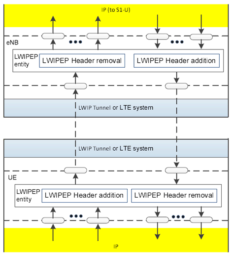
An LWIPEP entity delivers/receives the following LWIPEP PDU to/from a lower layer entity:
- LWIPEP data PDU.
4.3 Services Word‑p. 7
4.3.1 Services provided to upper layers Word‑p. 7
The following services are provided by LWIPEP to upper layers (i.e. IP):
- transfer of user plane data;
4.3.2 Services expected from lower layers Word‑p. 7
The following services are expected by LWIPEP from lower layers (i.e. LWIP Tunnel and E-UTRA):
- transfer of user plane data;
4.4 Functions Word‑p. 7
The following functions are supported by the LWIPEP sublayer:
- transfer of user plane data;
- identification of the DRB identity to which the LWIPEP SDU belongs.
5 Procedures Word‑p. 8
5.1 Data transfer procedures Word‑p. 8
5.1.1 UL data transfer procedures Word‑p. 8
When receiving an LWIPEP SDU from upper layers, the LWIPEP entity shall form the LWIPEP PDU as described in Section 6.1.
5.1.2 DL data transfer procedures Word‑p. 8
When receiving an LWIPEP PDU from lower layers, the LWIPEP entity shall:
-
if configured by upper layers to enable aggregation in DL:
- interpret the LWIPEP PDU as having both Key and Sequence Number fields included as described in clause 6.1;
- reorder received packets according to the Sequence Number field before delivering them to higher layers as specified in RFC 2890;
-
else:
- interpret the LWIPEP PDU as having Key field included as described in clause 6.1;
5.2 Handling of unknown, unforeseen and erroneous protocol data Word‑p. 8
When an LWIPEP entity receives an LWIPEP PDU that contains reserved or invalid values, the LWIPEP entity shall:
- discard the received PDU.
6 Protocol data units, formats and parameters Word‑p. 8
6.1 Protocol data units Word‑p. 8
6.1.1 General Word‑p. 8
An LWIPEP PDU is a bit string that is byte aligned (i.e. multiple of 8 bits) in length. In the figures in subclause 6.1, bit strings are represented by tables in which the most significant bit is the leftmost bit of the first line of the table, the least significant bit is the rightmost bit on the last line of the table, and more generally the bit string is to be read from left to right and then in the reading order of the lines. The bit order of each parameter field within an LWIPEP PDU is represented with the first and most significant bit in the leftmost bit and the last and least significant bit in the rightmost bit.
An LWIPEP SDU is a bit string that is byte aligned (i.e. multiple of 8 bits) in length. An LWIPEP SDU is included into an LWIPEP PDU from the first bit onward.
Only one type of LWIPEP PDU is defined, i.e. LWIPEP data PDU.
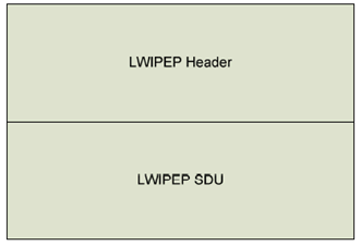
6.1.2 LWIPEP data PDU Word‑p. 8
An LWIPEP data PDU consists of the LWIPEP header and the LWIPEP SDU, as described in Figure 6.1.2-1. The LWIPEP header is populated as described in clause 6.2.1.
6.2 Formats and parameters Word‑p. 9
6.2.1 LWIPEP header Word‑p. 9
The LWIPEP Header is a GRE header as specified in RFC 2890 and has a fixed size of eight bytes (if only the Key field is included) or twelve bytes (if both the Key and Sequence Number fields are included).
The transmitter shall set the 5 LSB's of the Key field in the GRE header to the DRB Identity associated with the LWIPEP SDU and set the remaining MSB's to '0'. If instructed by RRC to enable aggregation in UL or DL, the transmitter shall in addition include the Sequence Number field as specified by RFC 2890 in the LWIPEP header. All other optional fields are unused, and the values of other fields shall be set as specified in RFC 2784 and RFC 2890.
$ Change History Word‑p. 10
![]()
![]()